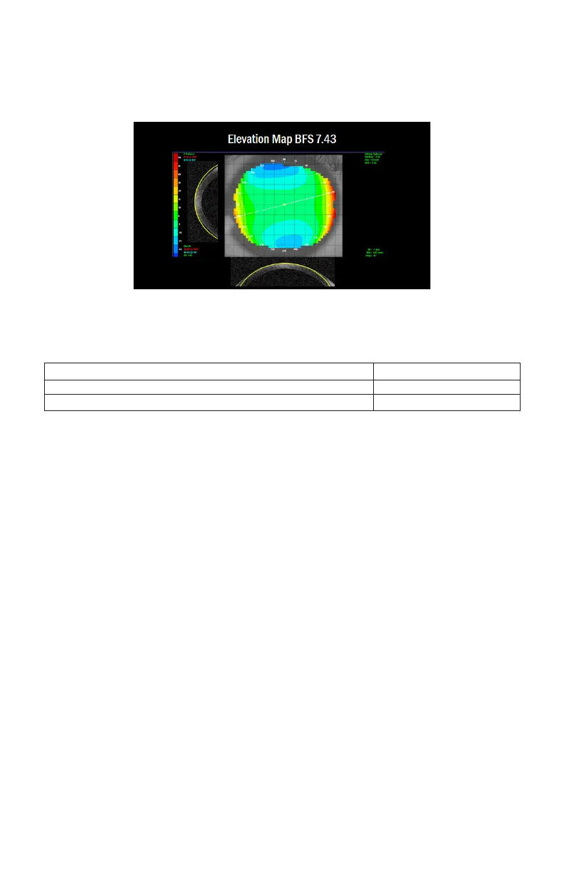
at a point 4 mm from the center of the plot, the local elevation may be observed
along the CRT lens chord length. If the total dierence is greater than 13 microns
on the two meridians at the 8 mm chord, a Paragon CRT Dual Axis® option may be
indicated.
When to consider Paragon CRT
®
or
Paragon CRT Dual Axis
®
:
Dierence In Flat & Steep Meridians at 8 mm chord Suggest Using is design
<30 Microns Paragon CRT®
>30 Microns Paragon CRT Dual Axis®
Calculating for CRT Dual Axis
®
from Elevation Dierences
1. Select the elevation plot feature on the corneal topographer. Look at the elevation
plot and observe the presence of signicant elevation dierence (BLUE vs. RED) in
the periphery of the plot.
2. Place the cursor on the shallow area (BLUE in color), 4 mm from the center of the
plot and record the number of microns below the reference sphere.
3. Repeat the measure 180 degrees away in the shallow area opposite to the rst
measurement.
4. Place the cursor on the elevated area (RED in color), 4 mm from the center of the
plot and approximately 90 degrees from the shallow area and record the number of
microns above the reference sphere.
5. Repeat the measure 180 degrees away in the elevated area opposite the rst
elevated measurement.
6. Calculate the average dierence from the elevated areas to the shallow areas.
7. If the average dierence is:
• less than 30 microns, a Paragon CRT Dual Axis® lens may not be indicated.
 Loading...