Chapter 4: Infrared Object Detection · Page 37
INSTALLING AND TESTING THE IR EMITTERS/DETECTORS
The SumoBot is specially designed to accommodate two IR emitter/detector pairs.
Before we install them, we need to assemble the IR LEDs into their shells, then bend and
trim the leads so that they don't become damaged or misaligned during competition.
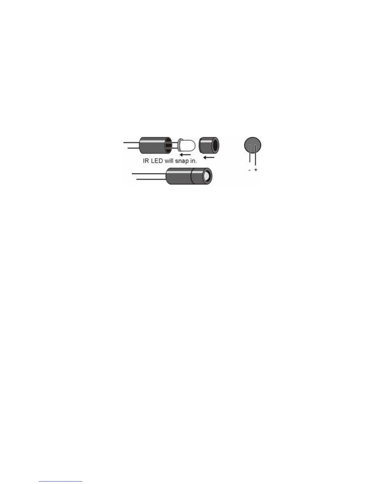
Figure 4.1 shows the assembly IR LED (clear) into the protective shell (standoff and
shield). The purpose of this assembly is to prevent stray IR from falling directly onto the
detector and causing a false positive reading.
Figure 4.1: IR LED, Standoff, and Shield Assembly
After assembly, bend the leads downward at a 90-degree angle so that when looking at
the back side of the shield, the positive (longer) lead is on the right. Trim the leads as
shown above.
Modify the detectors by trimming the leads to about 3/8" inches. This will cause the
detectors to sit lower and more firmly in the sockets, reducing the chance of
misalignment during competition.
 Loading...