Page 38 · SumoBot – Mini Sumo Robotics
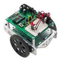
Figure 4.2: IR Detector
3
Trimming
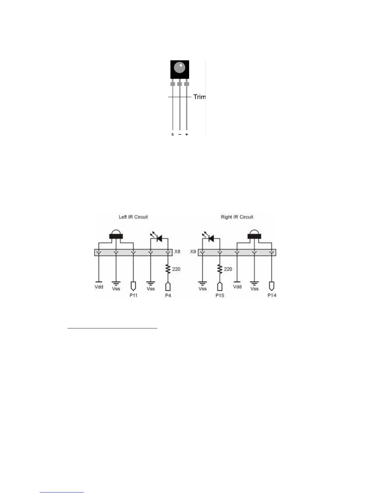
Figure 4.3 is the schematic for the SumoBot robot’s IR object sensing. Build this circuit
on your SumoBot. Note that the 220 Ω resistors are already built into the SumoBot PCB;
just plug in the IR emitters and your SumoBot will be ready. When aligning the IR
emitter "headlights" it's a good idea to angle them slightly outward to give the SumoBot a
wider field of vision.
Figure 4.3: SumoBot IR Object Detection Circuitry
3
Spare IR LEDs and detectors can be ordered Parallax at www.parallax.com
 Loading...