Chapter 4: Infrared Object Detection · Page 39
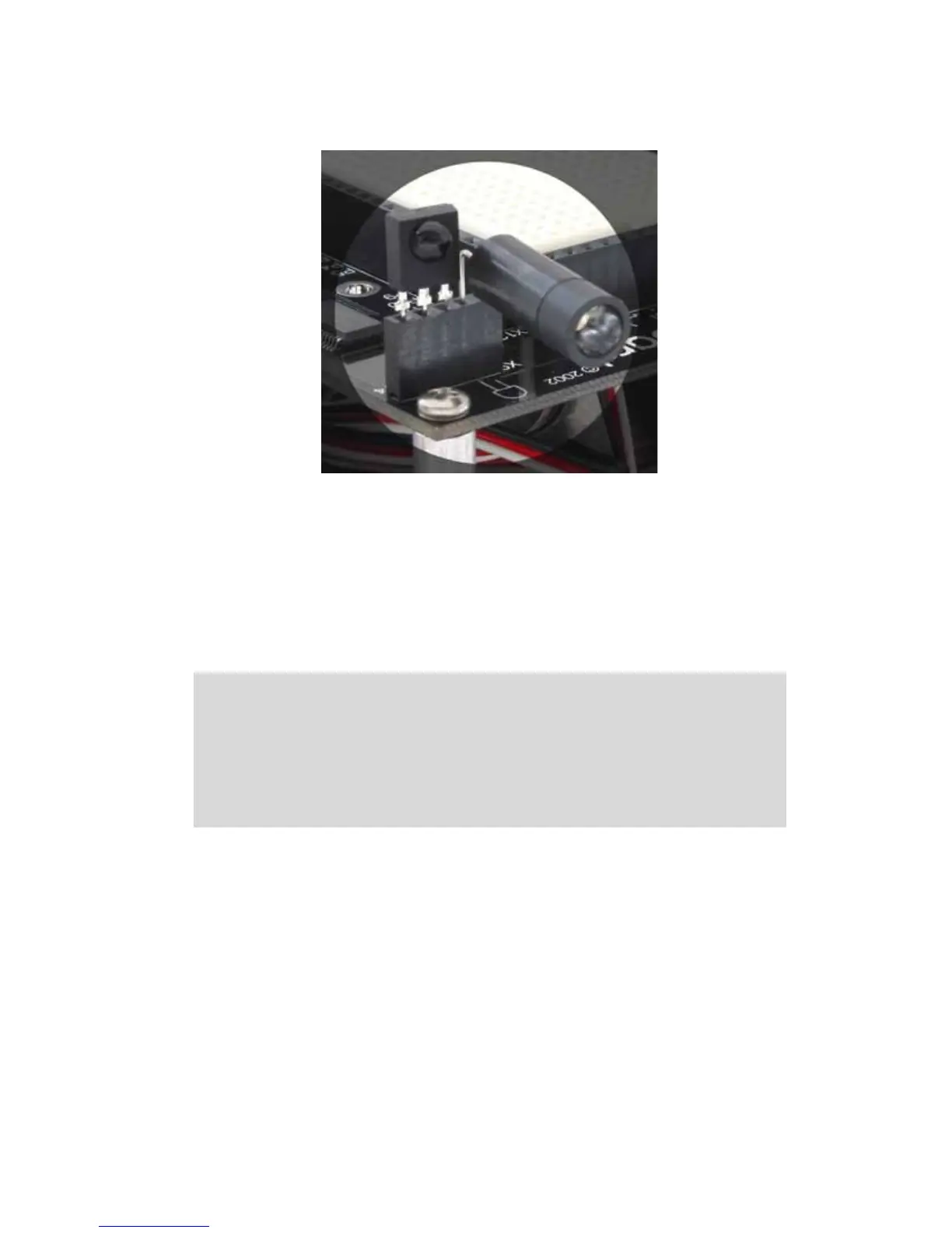
Figure 4.4: SumoBot IR Object Detection Components Installed
TESTING THE IR PAIRS
The key to making each IR pair work is to send one millisecond of unfiltered 38.5 kHz
FREQOUT harmonic followed immediately by testing the signal sent by the IR detector
and saving its output value. The IR detector’s normal output state when it sees no IR
signal is high (logic 1). When the IR detector sees the 38.5 kHz harmonic sent by the IR
LED, its output will drop from high to low (logic 0). Of course, if the IR does not reflect
off an object, the IR detector’s output simply stays high. Program 4.1 shows an example
of this method of reading the detectors
' SumoBot_4.1_IR_Sensor_Test.BS2
' {$STAMP BS2}
' {$PBASIC 2.5}
' -----[ I/O Definitions ]-------------------------------------------------
LfIrOut PIN 4 ' left IR LED output
LfIrIn PIN 11 ' left IR sensor input
RtIrOut PIN 15 ' right IR LED output
RtIrIn PIN 14 ' right IR sensor input
 Loading...