Commissioning – Controller Setup Advanced Installation
To access the additional functionality oered by the controller, the following settings must be activated and congured to match the
requirements of the installation:
Remote Stop / Start (Refer to page 25)
• Dipswitch conguration required
• Physical connection to remote switch required
Purge Economy (Refer to page 26)
Important Note: Only possible if dryer is installed directly after the compressor (no wet air receiver)
• Physical connection to compressor required
Remote Alarm Connection (Refer to page 28)
• General Fault Relay Indicates Power Loss / Dewpoint Alarm / Sensor Fault
• Physical connection required
Dedicated dewpoint alarm (Refer to page 29)
• Requires additional alarm relay (not supplied)
• Physical connection required
• Activation in service software required
4-20mA Dewpoint Retransmission (Refer to page 30)
• Physical connection required
• Additional components required
MODBUS connectivity (Refer to page 32)
• Physical connection to remote system required
• Setup via service software may be required
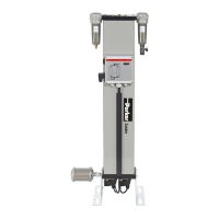
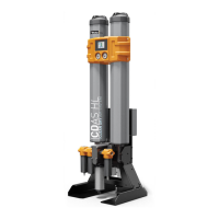
CDAS HL / OFAS HL / FBP HL Dryer Auxiliary Connections
CDAS HL / OFAS HL / FBP HL dryers can be connected to external control and alarm circuits using the dedicated terminals on the
lower terminal block of the PCB found inside the control box mounted at the rear of the dryer.
24
Medium Flow Compressed Air Dryers - IOMI.
When making these connections it is recommended that:
1. Cable lengths do not exceed 30m in length.
2. Twisted screened cables (0.75mm
2
) are used for the remote
start / stop, dewpoint retransmission and alarm relay
connections.
3. Low voltage cables are routed away from high voltage supply
cables
 Loading...