Parker Hannifin Corporation
Automation Actuator Division
Wadsworth, OH 44281
7
Automation
ET Series
PM-ET01/USA Stepper and Servo Driven Linear Actuators
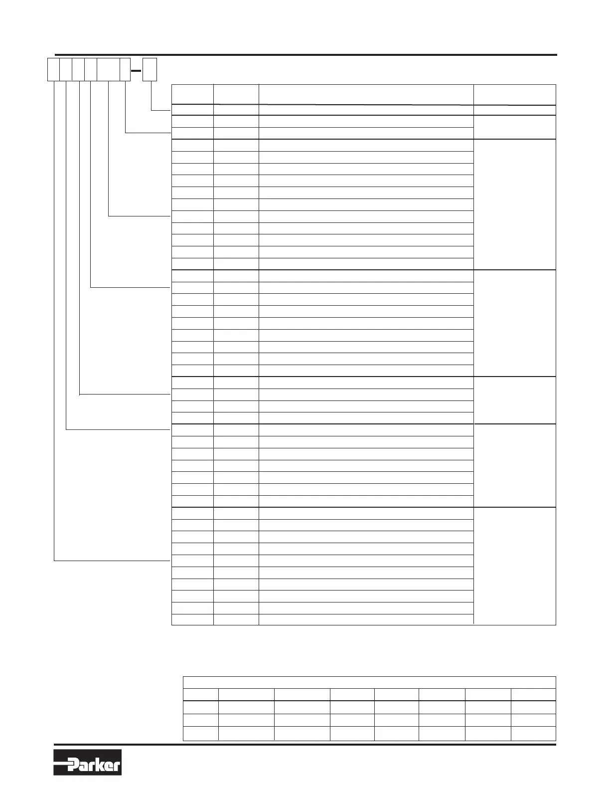
Ordering Information
F
M
E
A
600 L
A
A - Assigned by Factory
Omit - No linear Potentiometer
L - Linear Potentiometer
50 - ET32, ET50, (1.97)
100 - ET32, ET50, ET80, ET100 (3.94 in)
150 - ET32, ET50,ET80, ET100 (5.91 in)
200 - ET32, ET50, ET80, ET100 (7.87 in)
300 - ET32, ET50, ET80, ET100 (11.81in)
450 - ET32, ET50, ET80, ET100 (17.72 in)
600 - ET32, ET50, ET80, ET100 (26.62 in)
750 - ET32, ET50, ET80, ET100 (29.53 in)
1000 - ET50, ET80, ET100 (39.37 in)
1250 - ET80, ET100 (49.21 in)
1500 - ET80, ET100 (59.05 in)
Omit - No Brake
E E4 115 VAC w/ Fling leads and cable gland on lead screw
F E4 24 VDC w/ Flying leads and cable gland on lead screw
G E4 115 VAC w/ Brad Harrison conn. & 4m cable
H E4 24 VDC w/ Brad Harrison conn. & 4m cable
V - 115 VAC w/ Flying leads and cable gland on stepper
W - 124 VDC w/ Flying leads and cable gland on stepper
Y - 115 VAC w/ Brad Harrison conn. & 4m cable on stepper
Z - 24 VDC w/ Brad Harrison conn. & 4m cable on stepper
Omit - Standard (12 o’clock)
A - 3 o’clock
B - 6 o’clock
C - 9 o’clock
M D12 Male (Metric Standard)
F D12 Female
K D12 Male - Imperial
C D13 Clevis
S D13 Spherical Rod Eye
R
5
D15-20 Linear Rod Guide Module
X - Special
B
4
D3 Foot Mount (MS1)
C
4
D10 Rear Clevis (MP2-R)
D D4-5 Trunnion (MT4)
E
4
D9 Rear Eye (MP4)
F B48-49 Bottom Tap (MS4) (Standard)
G D8 Foot Side Lug
H
4
D7 Rear Flange (MF2)
J D6 Front Flange (MF1)
N
4
D7 Front & Rear Flange (MF1 & MF2)
X - Special
Symbol
Catalog
Description
Page
Design Series
Linear
Potentiometer
Stroke Length
(in mm)
Brake Option
7
Body
Orientation
6
Rod End
Cylinder
Mounting
4
Not available with Inline (L)
Motor Mounting.
5
Linear rod guide module may interfere with some switch groove orientations (Body Orientation A and C) on ET32, ET50 & ET80.
Not compatible with G, J, or N mounting options.
6
Switch Groove Orientation as viewed from Cylinder Shaft End. May decrease side load capacity. ET100 has switch grooves on all four sides.
7
Not available on ET32 or NEMA 23 motors. Options (E,F,G & H) not compatible with rear mounting options (B,C,E,H & N).
Options (V,W,Y & Z) not compatible damper or encoder.
Feature
Available Drive Ratio Combinations (Parallel only) (ET100 1:1 only)
Size S57-102 S83-135 S106-178 SM233B APEX605 APEX606 APEX610
32 1:1, 1:1.5 - - 1:1, 1:1.5 - - -
50 1:1, 1.5:1, 2:1 1:1, 1.5:1 - 1:1, 1.5:1 1:1 - -
80 - 1:1, 1.5:1, 2:1 1:1, 1.5:1 - 1:1, 1.5:1 1:1, 1.5:1 1:1, 1.5:1
 Loading...


