76
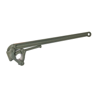
13.1 O-Lok
®
assembly instructions
Mechanical flaring and assembly
Safe method
Efficient procedure
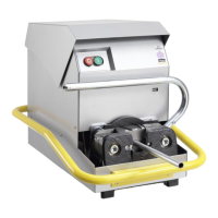
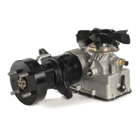
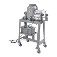
Use the Parflange
®
process
®
Parflange
®
machine:
• Select flaring pin in
accordance with tube
dimensions
• Use standard O-Lok®
flaring pin
• The flaring pin must not
feature any wear and tear,
damage or contaminants
• Keep the flaring pin clean
and lubricate it regularly
• Select the clamping jaws in
accordance with the tube
dimensions
• Use the special clamping
jaws for the flange seal
• The clamping surfaces must
not feature any wear and tear
or abrasion
• Only use original Parker
tools for O-Lok®
Observe limits for max. tube
wall thickness
• Insert flaring pin in tool holder
• Ensure that the automatic
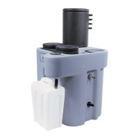
lubricating unit is filled with
EONIROMONTFLUESSX or
LUBSS
• Slide the nut over the
tube end and place the
support sleeve in the
clamping jaw half
• Fit the clamping jaw
halves together
• Insert the closed jaw
set into the conical
Insert the tube end until the
Secure the tube
• Open the clamping lever
•
Remove tube end from the
machine with clamping jaws
Loosen the jaws in the
separator by moving the tube
 Loading...