ENGLISH
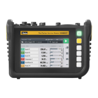
6.3.3 Manometer View
The manometer view displays the current, minimum and maximum
measured value as well as the measuring range full scale value for each
channel.
If more than four channels are active, you can scroll through the list.
88
Fig.24 Manometer view
Pos. Description
1 Designation of the active channel
2 Name of the active channel
3 Maximum measured value
4 Minimum measured value
5 Starting value for measuring range
6 Current measured value
7 Full scale (FS) value of measuring range
8 Drag indicator for minimum and maximum measured value
INFORMATION
The yellow range in the manometer indicates the defined warning
value, the red range the defined alarm value.
193
The Parker Service Master CONNECT V1.0/04/20
Operation
 Loading...