MTM Installation
www.parrinst.com
5
Reattach the side panel by slipping it back on and
tightening the nuts.
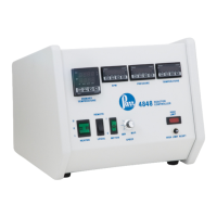
Close the controller and replace the two screws on
the top plate. Plug the 4848 controller back in, and
turn it on. The MTM display should read approxi-
mately zero when the motor is not turning. It is
useful to check that the settings on the display are
set correctly. Check the settings in this installation
guide against the settings on the controller.
Calibrating the MTM
1. 1. Turn the knob to zero, flip the local/remote
switch to “local”, and turn the motor switch on.
The MTM should show a value of zero. If it does
not, adjust the “tPoF” setting (press set and then
return until it shows tPoF) until it does read zero.
2. Turn the knob to full. The MTM should show a
value of 100.
3. Flip the local/remote switch to “remote”, and
put in a setpoint equal to the maximum stirring
speed on the Motor Control Module display. The
MTM should show a value of 100.
Pin Outs:
2084E Color: Attaches to:
Pin 1 Black Terminal Block 5 (power)
Pin 2 White Terminal Block 2 (power)
Pin 3
Pin 4 Red local / remote switch
(bottom position) (signal)
Pin 5
Pin 6 Black isolation board (pin 9)
(signal)
Pin 7
Pin 8
Pin 9
Pin 10
Pin 11 White Terminal Block 4 (RS-485)
Pin 12 Black Terminal Block 3 (RS-485)
Factory Default Settings - MTM
 Loading...