SERIE AW8000
11
CONNECTIONS
3CONNESSIONI
La correzione logaritmica del volume é già realizzata dallattenuatore
interno allamplificatore. Per una efficace pre-regolazione dei livelli, si
consiglia di porre a centro corsa il potenziometro e selezionare il livello
di uscita desiderato con il controllo pricipale MASTER VOLUME [7].
In questo modo, il potenziometro del controllo a distanza ha una capacità
di regolazione di 20 dB in aumento od in diminuzione rispetto al livello
prefissato con il controllo MASTER VOLUME.
The volume logarithmic adjustment is already performed by the
attenuator built into the amplifier. For an effective level pre-adjustment,
the VR should be set to the mid-range and the output level should be
selected as required by means of the MASTER VOLUME control [7].
In this way, the remote control VR has an adjustment capacity of 20 dB
above or below the level preset with the MASTER VOLUME control.
ESEMPIO:
R1 = 6K8
R2 = 27 K
Attenuazione con contatto A chiuso:
40 x 27 K (27 K-6K8) = 32 dB
Scegliere R1 o R2 in modo che
30 kΩ ≤ R1 + R2 ≤ 50 KΩ
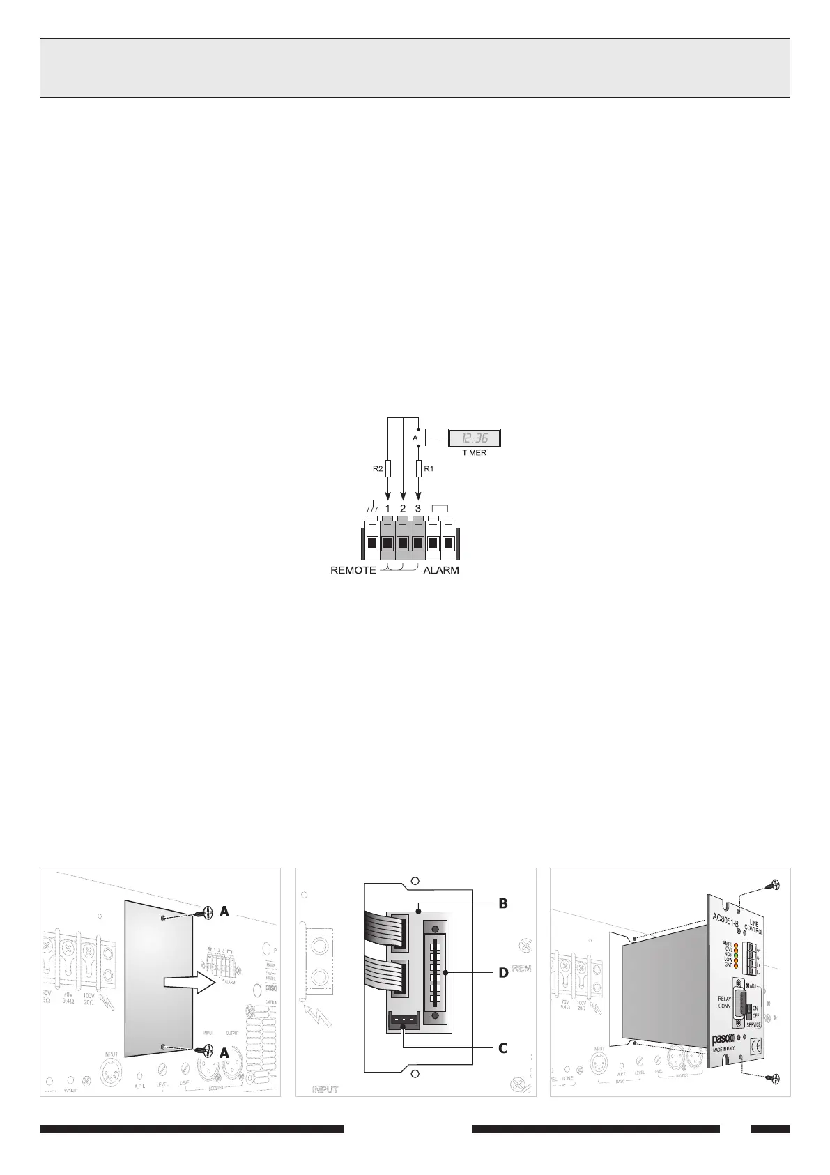
Fig. 3.6.5
EXAMPLE:
R1 = 6K8
R2 = 27 K
damping with closed A contact:
40 x 27 K (27 K-6K8) = 32 dB
Choose R1 or R2 in order that
30 kΩ ≤ R1 + R2 ≤ 50 KΩ
Controllo del livello di uscita su due livelli
La regolazione, in questo caso, avviene tramite un partitore resistivo
inserito da un contatto a secco come in configurazione di figura 3.6.5.
Quando il contatto A è aperto, l'attenuazione è nulla.
Quando il contatto A è chiuso, il segnale è attenuato di una quantità
data dalla formula:
attenuazione (dB) = 40 x R
2/(R1+R2)
Output two-level control
In this case, adjustment is performed by means of a resistive divider
which is triggered by a dry contact as shown on Figure 3.6.5.
When contact A is opened, damping is zero.
When contact A is closed, the signal is attenuated by a value resulting
from the following:
attenuation (dB) = 40 x R2/(R1+R2)
Questo controllo trova la sua applicazione in impianti con diffusione in
luoghi aperti, per ridurre il livello sonoro nelle ore serali e notturne e
l'attuatore di inserzione è il contatto di un timer.
This control is switchable for outdoor sound systems in order to reduce
the sound level in the evening and at night; the triggering actuator is a
timer contact.
3.7 MODULI
Per estendere le prestazioni dellapparecchio, è stata prevista una serie
di moduli da inserire nellapposito vano [11].
Lapparecchio viene fornito con un pannellino di chiusura standard.
Per inserire i moduli accessori nellamplificatore, operare come segue:
1. togliere le due viti (A) che fissano il pannellino di chiusura al posteriore
dellamplificatore (figura 3.7.1).
2. Estrarre il pannellino e sfilare dai distanziali in plastica posti sul lato
interno il circuito (B).
3. Posizionare il circuito (B) come illustrato in figura 3.7.2.
NOTA: nel caso si dovesse utilizzare il modulo AC8051-B, collegare la
piattina al connettore (C).
4. Fissare il modulo nel connettore (D) e, sfruttando gli scarichi presenti
sul margine dellapertura, inserire il modulo così collegato allinterno
dellamplificatore (fig. 3.7.3).
5. Fissare il pannello del modulo al posteriore dellamplificatore riutilizzando
le viti precedentemente rimosse.
3.7 MODULES
To extend the features of the equipment, a range of modules to be
inserted into the compartment provided for this purpose has been
envisaged [11]. The equipment is supplied with a standard panel for
closing the compartment.
To plug the accessory modules into the amplifier, proceed as follows:
1. Remove the two screws (A) that fix the panel covering the
compartment to the rear of the amplifier (Figure 3.7.1).
2. Remove the panel and pull the circuit out of the plastic spacers situated
on the inside (B).
3. Position the circuit (B) as illustrated in Figure 3.7.2.
NOTE: If you wish to use module AC8051-B, connect the flat twin
cable to connector (C).
4. Plug the module into the connector (D) and, exploiting the recesses
present on the edge of the opening, insert the plugged-in module
inside the amplifier (Figure 3.7.3).
5. Secure the panel of the module to the rear of the amplifier using the
screws that had previously been removed.
Fig. 3.7.1 Fig. 3.7.2 Fig. 3.7.3
11-544.p65 08/02/02, 10.4711
 Loading...