SERIE AW8000
8
CONNECTIONS
3CONNESSIONI
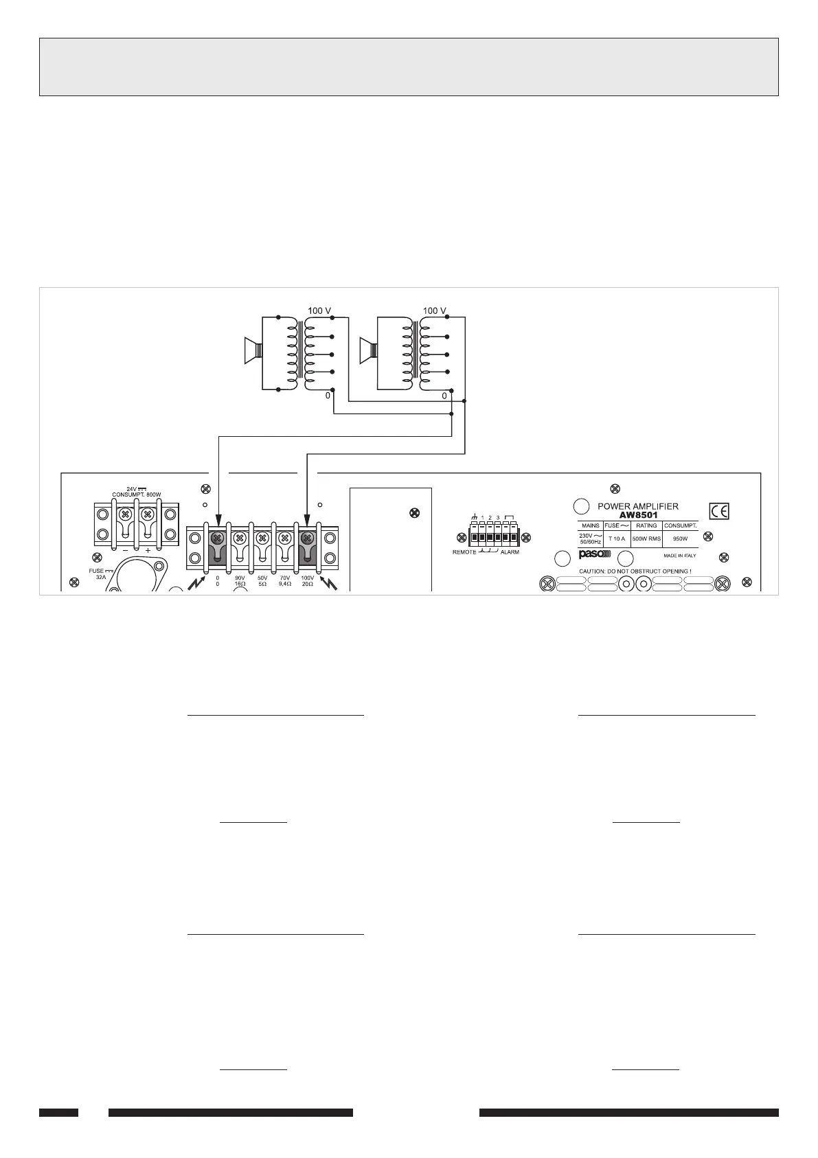
3.4.2 Sistemi a tensione costante
Nel caso di impianti con un gran numero di diffusori e/o con distanze tra
amplificatori ed altoparlanti molto elevate é preferibile utilizzare un sistema
di distribuzione a tensione costante (definito anche ad alta impedenza).
In questo tipo di impianto, i diffusori, provvisti di trasformatori di
adattamento di impedenza, sono tutti collegati in derivazione alla linea
(vedi es. di Fig. 3.4.3); questo particolare rende di facile realizzazione
limpianto e, nel caso in cui un altoparlante dovesse per qualche motivo
scollegarsi dalla linea, il resto dellimpianto proseguirebbe nel suo regolare
funzionamento. Le tensioni costanti disponibili in uscita dallamplificatore
sono 90, 50, 70 e 100 V.
Fig. 3.4.3
3.4.2 Constant voltage systems
When a large number of speakers is used and/or the speakers are
placed far from the amplifiers, constant voltage distribution system
should be used (also known as high-impedance systems).
In this type of system, the speakers are fitted with impedance
adaptation transformers and all of them have shunt line connections
(see example of Fig. 3.4.3).
This simplifies the layout of the system and if, for any reason, a
loudspeaker is disconnected from the line, the rest of the system will
continue to work properly. The constant voltages output from the
amplifier are 90, 50, 70 and 100 V.
Calcolo del numero di diffusori (tramite le potenze)
Si supponga di avere definito sia l'amplificatore (cioè la sua potenza di
uscita) che il tipo di diffusore con relativa potenza assorbita.
In questo caso il massimo numero di diffusori collegabile sulla linea è
determinato dalla seguente formula:
Esempio: si utilizzino un amplificatore AW8501 con plafoniere modello
Paso C52/10-T. L'amplificatore è in grado di erogare una potenza pari
a 500 W, mentre un diffusore assorbe una potenza di 10 W.
Per sapere quanti diffusori sono collegabili alla linea di uscita si calcola:
Determining the number of speakers (through power values)
If both the amplifier (i.e. its output power) and the type of speaker
with its power consumption have been established, the maximum number
of speakers which may be connected to the line may be determined as
follows:
Example: in a system including a AW8501 amplifier with ceiling
speakers type Paso C52/10-T is used, the amplifier can supply 500 W
power whereas the speaker has a power consumption of 10 W.
The number of speakers which may be connected to the output line is:
500 W
10 W
numero diffusori = = 50
numero diffusori =
potenza amplificatore
potenza diffusore
number of speakers =
amplifier power
speaker power
500 W
10 W
number of speakers = = 50
Calcolo del numero di diffusori (tramite le impedenze)
Se il dato disponibile è l'impedenza del diffusore, il numero massimo di
diffusori collegabili ad una linea è:
dove l'impedenza nominale dell'amplificatore
ricavabile dalla
tabella 3.4.1.
Esempio: si utilizzino un amplificatore AW8501 con diffusori tipo
Paso C48-T, che presentano una impedenza pari a 833 ohm.
Dalla tabella 3.4.1 si trova che l'impedenza nominale di carico della linea
a 100 V è pari a 20 ohm.
Quindi:
Determining the number of speakers (through impedance)
If the impedance of the speaker is known, the maximum number o
speakers which may be connected to the line is:
where the amplifier rated impedance may be determined referring to
Table 3.4.1.
Example: If a AW8501 amplifier is used with speakers type Paso
C48-T having a 833 ohm impedance, the rated load impedance of the
line at 100 V may be determined from Table 3.4.1 as being equal to
20 ohm.
Thus:
number of speakers =
speaker impedance
amplifier impedance
833 Ω
20 Ω
number of speakers = = 41
numero diffusori =
impedenza diffusore
impedenza amplificatore
833 Ω
20 Ω
numero diffusori = = 41
11-544.p65 08/02/02, 10.478
 Loading...