Part No. 1101-7119-01 © 2014 PAX Water Technologies, Inc.
PAX Water Mixer (PWM100)
Installation/Operation Manual
6
5. Facilities Requirements
The following requirements must be provided at the installation site. This manual is not intended
to cover the set-up of these facilities.
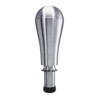
PWM100 ASSEMBLY
REQUIREMENT DESCRIPTION
Line Power
Dedicated 120 VAC, 60 Hz, single phase, 20 amp GFCI-
protected circuit.
Safety Disconnect Switch
The safety disconnect switch must be a 3R certified type, properly
marked and installed in accordance with all electrical codes,
state, local and OSHA requirments.
Junction Box 3R located in accordance with local codes.
Electrical Conduit
The PAX Water Mixer cable is a 3 wire cable set, 0.5” (12.7 mm)
in diameter. Use electrical conduit (3/4” or 20 mm) from the
tank penetration to the junction box, and from the junction box to
the safety disconnect switch.
Strain Relief
Designed for a 1.025” (26 mm) hole penetration and able to
support 50 lbs (22.7 kg).
 Loading...