PAGE 3
Wiring methods shall be in accordance with the National Electrical Code (ANSI/NFPA70),
local codes, and the authorities having jurisdiction.
Unit installation / test
Following the completed installation of this equipment, no further maintenance or testing is required.
It is advisable to ensure that any third party backup power supplies or recovery procedures are checked regularly
to ensure that the operation of the Paxton system is not compromised.
Maintenance
FCC Compliance
This device complies with Part 15 of the FCC Rules. Operation is subject to the following two conditions:
(1) this device may not cause harmful interference, and (2) this device must accept any interference received,
including interference that may cause undesired operation. Changes or modications not expressly approved by
the party responsible for compliance could void the user's authority to operate the equipment.
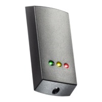
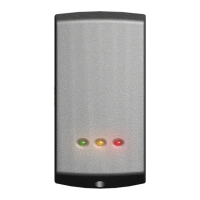
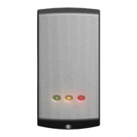
When chosing a location for the reader, ensure that it is a least 12 inches from other readers. This will include
readers mounted on the other side of the same wall as the radio signal will cause interference and reduce the read
range. The reader should not be used on metal surfaces as the reected signal will also reduce the read range.
Standard Unit - Drill a hole in the surface for the rear data cable. Secure the unit to the surface with three screws
as per tting diagram on page 1. 3 suitable screws and xings are provided for tting the unit to a wall. Ensure
the data cable has free access at the rear.
A choice of black and white covers are also provided. Hook the required cover over the top of the reader, press
home at the bottom and secure with the single xing screw.
Screw Terminal Unit - The adapter (310-750-US) is mounted to a standard backbox using the xing screws
provided. The 75mm reader is then mounted onto the adapter using the tting kit provided with the reader.
The reader will bleep and all the LEDS should display after powering on the control unit. Presenting a user card to
the reader will cause the LEDs to briey change to a single Green or Red LED.
Check the following FAQs section for assssistance if any problems are encountered.
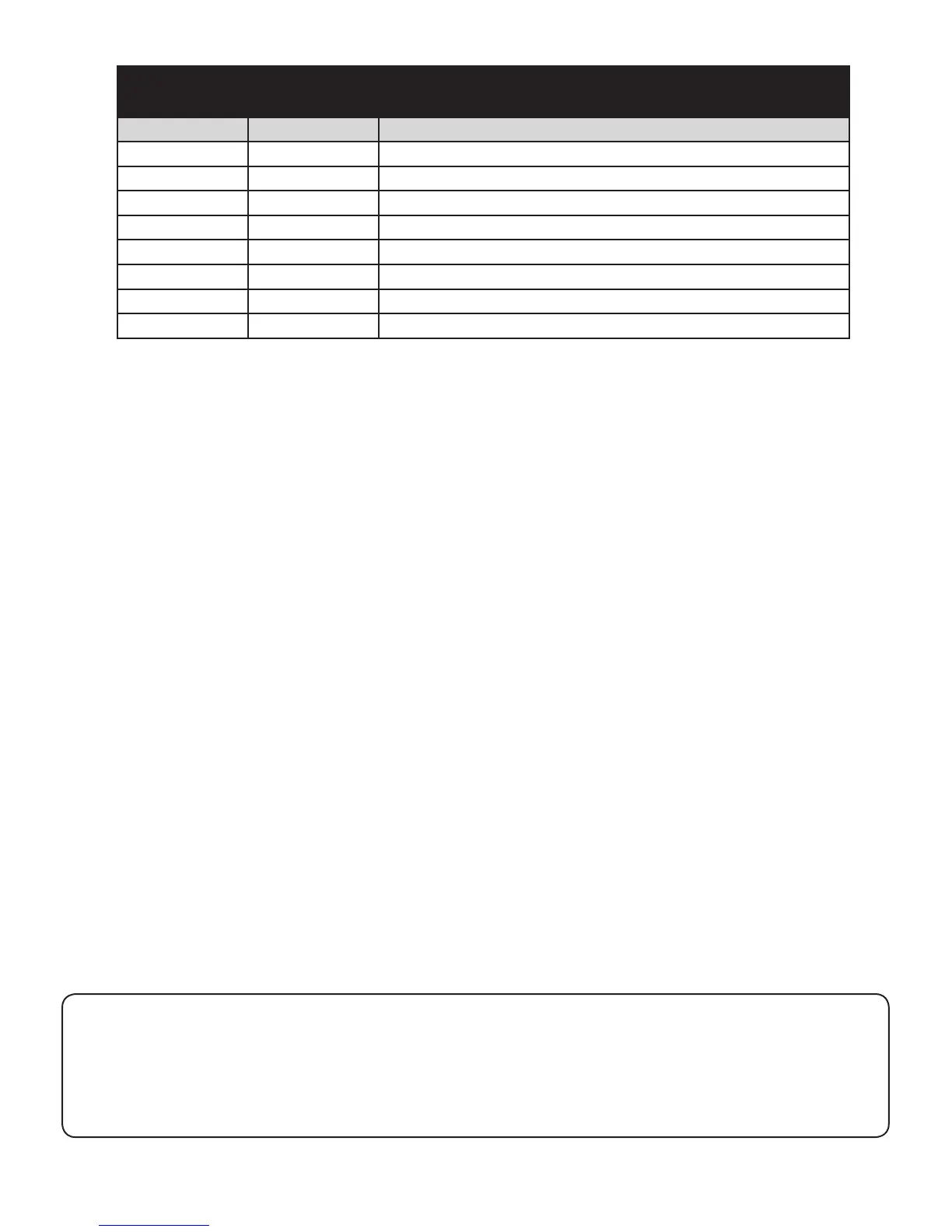
Option Part number Description
P50 Fitting Kit fk1-085 (5) Cable clips
(3) No6 x
3
/4 woodscrew - zinc
(3) Wall plugs 22 mm
(1) 8 mm x 3 mm small self tapping screw - zinc
P75 Fitting Kit fk1-084 (5) Cable clips
(3) No8 x 1 woodscrew - zinc
(3) Wall plugs 35 mm
(1) 8 mm x 3 mm small self tapping screw - zinc
Fitting Kit
 Loading...