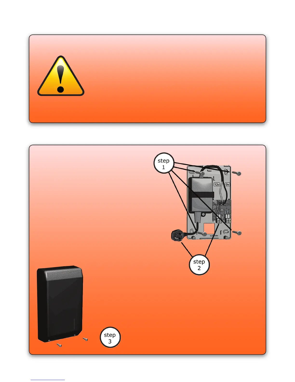
Step 1: Mark the mounting points for the
power supply. Drill the four holes, t the
rawl plugs and screw the power supply to
the wall.
Step 2: Run the black/red cables from
the reader to the power supply. Attach
the red wire to the 12v power supply
terminal, and the black wire to the 0v
power supply terminal. The cables can
be secured in place using the cable clips
provided. Please ensure that the cable is
not damaged when tting the cable clips.
Fit the power lead provided.
Step 3: Using the guides provided, make a gap
for the cables on the power supply cover. Fit
the cover, feeding the cables through the gap.
Do not connect the power supply to the mains
until the lock is tted. Once this is done,
power the system up, and start programming
the system.
Wiring Information
Black 0v power supply wire
Red 12v power supply wire
Blue/Mauve Exit button wires
Green 0v lock wire
Yellow 12v lock wire
The lock and power wires must be connected to the correct
polarity, otherwise the system could be damaged.
PAGE 5
 Loading...