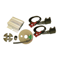
SMART-FIRE FITTING INSTRUCTIONS
WARNING: THIS SYSTEM PRODUCES VERY HIGH VOLTAGES,
ALWAYS SWITCH OFF BEFORE WORKING ON THE SYSTEM.
IMPORTANT NOTES:
BEFORE FITTING, PLEASE READ THESE INSTRUCTIONS
CAREFULLY, INCLUDING THE NOTICE ON PAGE 16.
This system is designed to work only with the special digital ignition coil
provided with the system. 5K resistor plug caps as supplied with the
system should be fitted to the h.t. leads. Alternatively, resistor spark
plugs can be used. resistor plugs & resistor caps can be used, although
it is not necessary to use both. Attempting to run the system without
resistor type caps or plugs will result in excessive radio frequency
interference (r.f.i.), which may cause bad running, misfiring and loss of
ignition. For reliability, copper or steel cored h.t. lead should be used, we
do not recommend using carbon fibre leads. This ignition is a wasted
spark system, therefore both plugs fire at the same time.
These instructions are a general guide for installing the system to
various machines and therefore it may be necessary to modify the length
or routing of some wires in order to complete the installation. All
connections should be made using good quality crimped or soldered
connections; twisted wires will not give satisfactory operation. Wiring
should be trimmed to the correct length, excess wire should not be
coiled up as this can affect the correct running of the ignition system. If
electric welding is to be carried out, the ignition module should be
disconnected and its connectors covered with insulation, to help prevent
stray sparks from damaging the module. If in doubt, remove the unit from
the machine.
1. Remove the battery cover.
2. For safety, disconnect the battery (preferably both terminals).
3. Remove the points cover.
4. Remove the 10mm bolt holding the automatic advance assembly.
5. Remove the two screws holding the points plate and keep in a safe
place. Disconnect the points wires (normally coloured blue &
yellow) from the wiring harness and remove the complete contact-
breaker assembly.


 To Next Page
 Loading...