PAGE 4
SENSORS AND INSTRUMENTATION FOR MACHINE CONDITION MONITORING
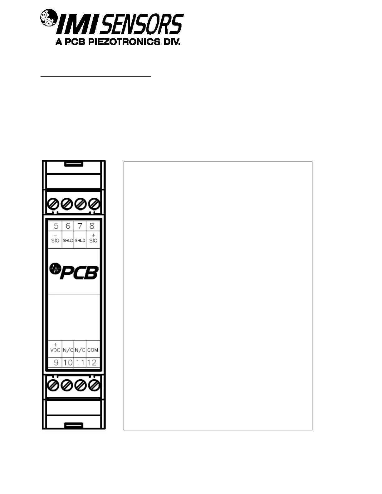
Connector and Pinout Diagram
The 682M57 and 682M74 use plug-in type screw terminal connectors for all input and output connections.
Strip off ~8mm of insulation from the connection wire ends. Using a small screwdriver, remove the terminal block
from the enclosure in either the up or down direction, terminate the wire in the correct location. Do not exceed a
torque of 0.5Nm. Do not leave excess uninsulated wire which can short to adjacent wiring. Re-install the terminal
block.
This easy to assemble connection method allows devices to be exchanged easily and the electrical connection to
be visibly isolated.
Pin Descriptions:
Pin 5: Sig –
Negative Charge Input Signal
Pin 6: Shield
Attach cable shield if available. This pin
connects to the Din Rail bar that the amplifier is
mounted on.
Pin 7: Shield
Same as Pin 6
Pin 8: Sig +
Positive Charge Input Signal
Pin 9: VDC +
Attach to the positive of ICP
®
power supply
Pin 10: N/C
No Connection
Pin 11: N/C
No Connection
Pin 12: Common
Attach to the negative of ICP
®
power supply