The two Flap servos are located within the gear bays. The 4-40 pushrod runs
underneath the gear leg (when retracted) and passes through the balsa sheeting and
out to the horn located in the top of the flap. The Flap is Bottom hinged.
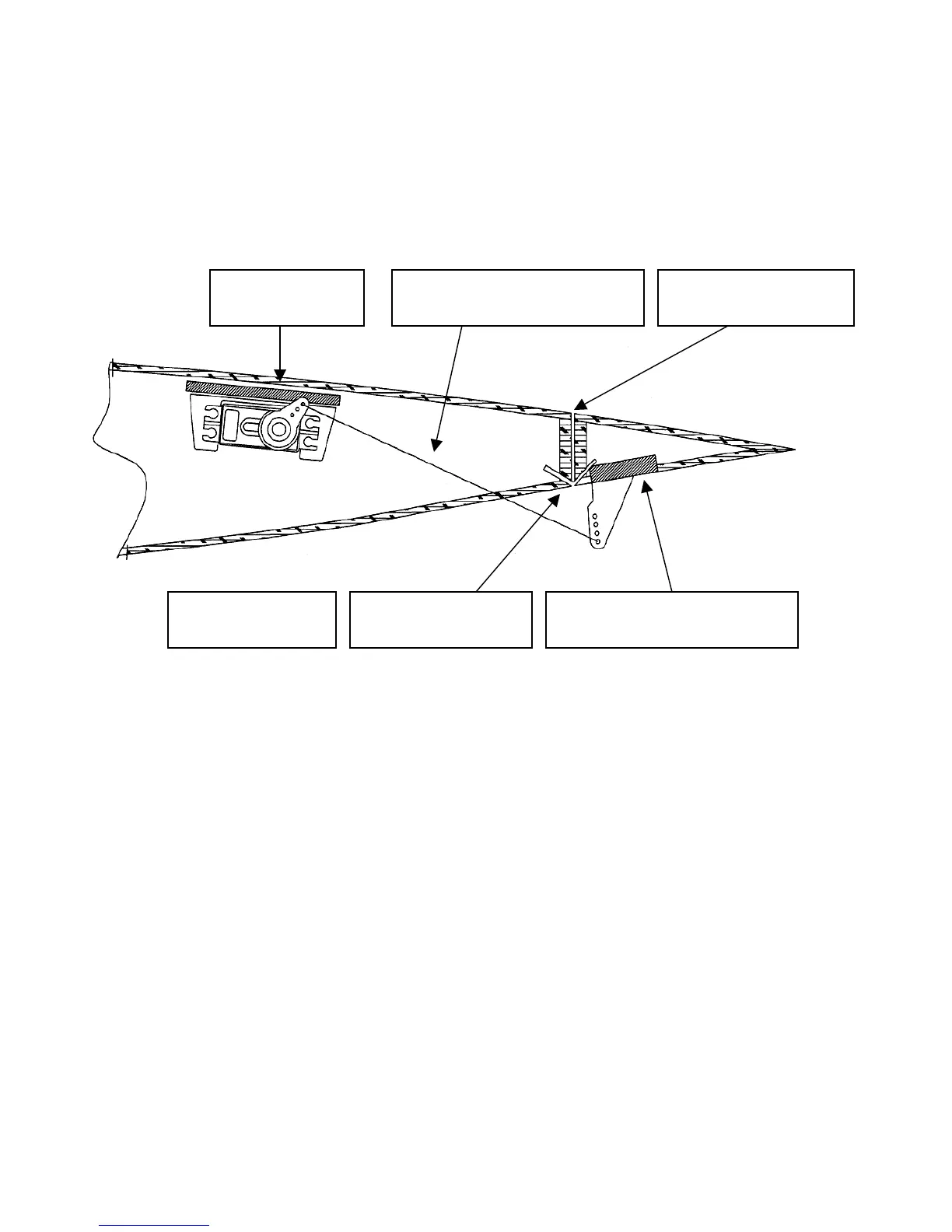
Flap Detail Diagram
ote position of servo arm
and horn when flap is raised
ote there is no bevel
on the flap LE.
Flap is hinged on the
bottom as shown.
Steel control horn mounted on
¼ ply base embedded in wing
Servo mounted
in ServoPr
This drawing is
not drawn to scale
The servo is located between WR3 and WR2just in front of the retract air cylinder.
The horn is oriented towards the top sheeting as shown in order that the pushrod has a
straight shot to the control horn. It is important that you make sure your geometry of
the pushrod is correct. A flap, unlike an aileron or elevator is not at neutral travel in
the center rather it is at the end of its travel in one direction (raised) and then passes
through the mid way point on its way to full deployment. Ideally, the geometry of the
servo arm, pushrod and control horn should be at right angles when the flap is at half
travel. Note relative position of the control horn clevis pivot point and hinge point
location.
When the location of the control horn is determined, Imbed a ¼ x ¾ x 1-1/4 Plywood
Control horn base flush with the sheeting. First cut away the balsa skin then remove
enough foam underneath for the base to sit level. Use 5-minute epoxy
The control horn is mounted to the base with the supplied button head screws.
33
 Loading...