25
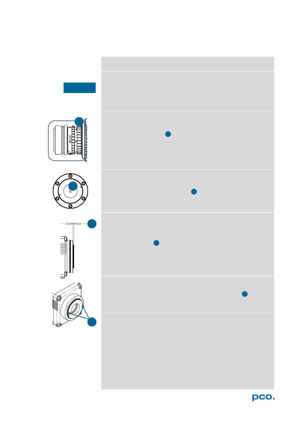
A3.2 CHANGE FROM F-MOUNT TO C-MOUNT
How to change the optical input from F-mount to C-mount.
MECHANICAL DAMAGE OF THE C-MOUNT RING
Tightening the hexagon socket setscrews too tight will permanently
damage the C-mount ring.
Use a torque wrench and select a maximum torque of 1 Nm
to tighten the hexagon socket setscrews.
Step 1: Remove F-mount adapter
Turn the black lock ring counterclockwise to loosen the F-mount
adapter and then unscrew it.
Step 2: Insert C-mount ring
Carefully screw the C-mount ring clockwise. The two hexagon
setscrews must be visible on the outside.
Step 3: Adjust flange focal distance
In order to reach the standard support dimension of C-mount (17.526
mm), screw in the C-mount ring so far that it protrudes outwards a
distance of 1.8 mm .
For fine adjustment use a suitable lens with large aperture.
Step 4: Fix the C-mount ring
To fix the C-mount ring, tighten both hexagon setscrews (1.5 mm
hex key) to a maximum torque of 1 Nm.
Limitations of C-mount Lenses
Keep in mind that C-mount lenses could cause shadings at the edges
of big sized sensors. Most C-mount lenses are able to illuminate a
maximum image circle of 11 mm (2/3”), 16 mm (1”) or 22 mm (4/3”)
diameter only. The pco.edge bi has a sensor diagonal of 18.8 mm, it
follows that you have to use the ROI function for a shade less image
while using the C-mount adapter with the two smaller C-mount
diameters.
NOTICE
 Loading...