6
3. SYSTEM COMPONENTS
The camera system includes the following parts.
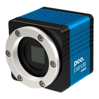
Camera
• F-mount / C-mount optical connection
• For standard C-mount / F-mount lenses and adapters
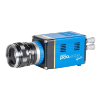
Rear Panel
• USB 3.1 Type C connector
• LED indicates camera status (see A1.3)
• SMA connectors
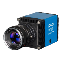
Serial Number Tag
• 1x 1/4"- 20 UNC
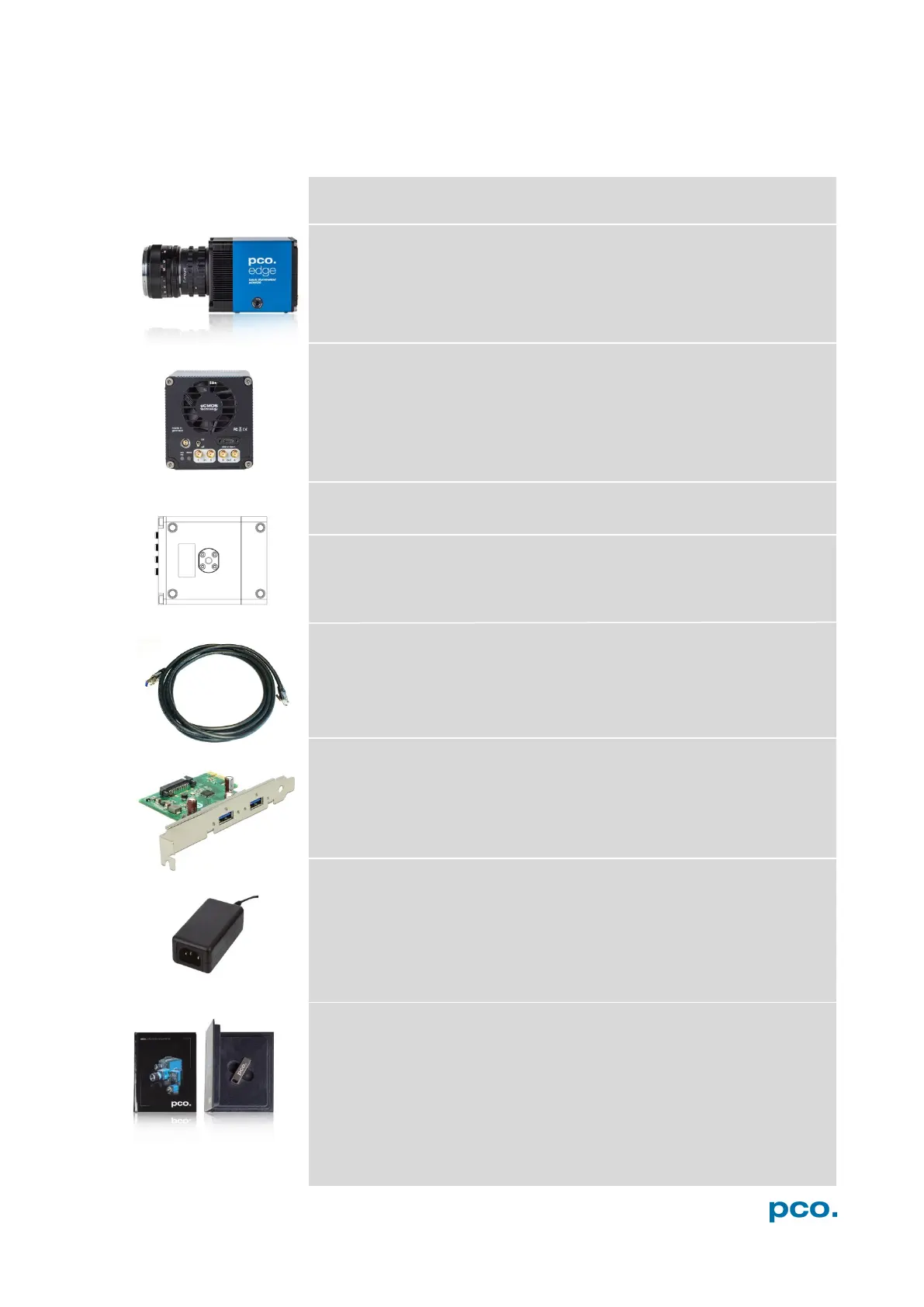
• USB Type A / USB Type C screwable cable
• Length 3 m
USB 3.0 / 3.1 Gen1 Interface Card
• 2x USB Type A socket
• PCI Express x1 V2.0
Power Supply & Power Cord
• Output: 24 VDC / 36W / 1.5A
• Connector: Lemo FGG.0B
• Voltage input: 115 VAC - 230 VAC; IEC 60320 C14 plug
• Power cord IEC 60320 C13
Digital Camera Tools (USB flash drive content)
• pco.camware: software for camera control & image acquisition
• Camera driver & tools
• Software Development Kit (SDK) & demo programs in C and C++
 Loading...