10
Bit 3 - "motor alarm (M2 stall)"
Bit 3 is set to "1" if the DHC detects a stall in the
M2 direction. The M2 direction is associated with
the ▼ button when the DHC is operated in the
manual mode.
NOTE: When bits 2 and 3 are both set to "1", this
indicates a stall detected in both directions. The
alarms can be cleared mechanically at the actuator,
but also by powering the unit down and back up.
This allows the DHC to attempt moving the
actuator. A power down sequence can also be
simulated via the bus using the PACS
®
Reset
parameter (see Section III).
Bits 4 - "open limit switch alarm" (DHC-400 only)
The actuator's limit switches should be set outside
of the open and closed positions so that the DHC
controller can accurately position at 0% and 100%.
Since the DHC-400 requires the limit switches be
connected to the controller, it will detect when the
limit switch is reached and sets bit 4 to "1"
accordingly. While this causes a fault condition,
the unit flashes the OPEN indicator rather than one
of the FAULT indicators.
Bits 5 - "close limit switch alarm" (DHC-400 only)
Bit 5 performs a similar function as bit 4 for the
close limit switch. The CLOSE indicator flashes,
rather than one of the FAULT indicators, when the
close limit switch is reached.
Bit 6 - "aux open limit alarm"
Mechanical auxiliary switches are commonly
installed in actuators to provide a signal when the
actuator's position reaches a critical point before
full open. Bit 6 can be used to eliminate the need
for such a switch. The desired position can be set
using the AUX OPEN OUTPUT mode from the
DHC control panel. Alternatively, the aux open
position can be precisely set using the Aux Open
Position parameter (see Section III). Bit 6 is set to
"1" whenever the actuator's position is between the
aux open position and the open position.
Technically, this alarm is not considered a fault
condition, and the DHC flashes the AUX OPEN
OUTPUT light whenever bit 6 is "1".
Bit 7 - "aux close limit alarm"
Bit 7 performs a similar function as bit 6 for the
aux close position. The aux close position can be
set with the AUX CLOSE OUTPUT mode on the
DHC controller, or by using the Aux Closed
Position parameter (see Section III). Bit 7 is set to
"1", and the DHC flashes the AUX CLOSE
OUTPUT light, whenever the actuator's position is
between the aux close position and the closed
position.
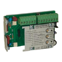
MODE
00CB SING
The Mode parameter is a SING byte value that
indicates what mode of operation the DHC controller is in.
Since the bus cannot control the DHC outputs to the
actuator unless the DHC controller is set to the AUTO
mode, it can be useful to monitor this parameter. The
values of the Mode parameter are listed below, and are the
only values returned by the DHC controller.
decimal value DHC mode
0 AUTO
1 MANUAL
2 CLOSE
3 OPEN
4 COMMAND TYPE
5 AUX CLOSE OUTPUT
6 AUX OPEN OUTPUT
7 LOSS OF COMMAND
10 PACS
®
MANUAL
11 POSITION OUT CAL (Close)
12 POSITION OUT CAL (Open)
In the following example, $0B (11 decimal)
indicates that the DHC is in the POSITION OUT CAL
(Close) mode.
PACS
®
Command (RS#CB):
50 00 CB
Returned Data (example):
0B
DHC controllers feature an override input that
allows an operator to manual control the actuator from an
external local/remote station. When override operation is
enabled, the Mode parameter reports the mode of operation
the DHC was in prior to override control. If bit 7 of the
Override Control parameter is "0", the Mode parameter
indicates the active mode of operation. If bit 7 of the
Override Control parameter is "1", the mode of operation
indicated by the Mode parameter is not active, and the
DHC is in override operation. If a local/remote station is
used, both parameters will need to be monitored to
determine the DHC controller's mode of operation.

 Loading...