ASAHI/AMERICA, INC 655 ANDOVER STREET LAWRENCE, MA. 01843 TELEPHONE 800-343-3618
Location: assembly/manuals Series 92 A/C Modulating Svc Manual Gen II Rev. A 11/15/19
Page 18 of 26
Fault Indicators
The DHC-100 detects various fault conditions that prohibit the unit from
controlling the actuator. A combination of the three Fault indicators (red, yellow,
and green) will turn on or flash to indicate a specific detected fault. If an
appropriate relay option module is installed, the Fault relay output on the option
module will turn off (indicating a fault) when any of the Fault indicators turn on or
flash. A communications option module can also read the specific conditions
causing a fault. Note that a fault condition DOES NOT disable the motor outputs
when manually controlling the actuator with the adjust buttons; while useful in
troubleshooting, care should be exercised when operating the motor under a fault
condition. The OVERRIDE mode can also operate the motor when a fault
condition exists – see OVERRIDE MODE for details.
Note that the indicators may not indicate ALL the fault conditions that may exist.
This means that when the indicated fault is corrected, the unit may display
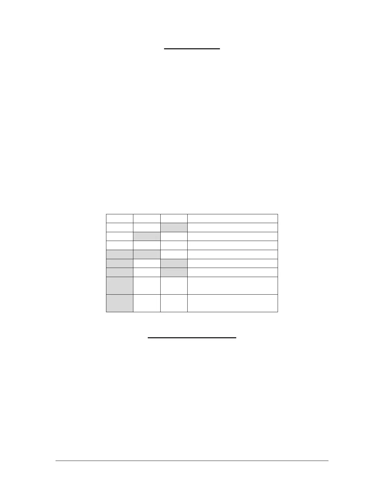
another fault that has not been corrected. The table below provides a summary
of the Fault indications which is followed by a description of each fault.
Motor 1 No Motion (stall)
Motor 2 No Motion (stall)
Feedback Alarm and
Loss of Command
Feedback Alarm and
Command out of Range
Motor 1 No Motion (stall)
A fault condition is detected when no actuator motion is detected while the Motor
1 output is turned on. The fault condition will disable the Motor 1 output only, and
the fault is cleared when the DHC-100 detects a motion greater than 1.5 in
either direction. The fault can be cleared if 1) the command signal commands a
Motor 2 operation, 2) manual operation with the adjust buttons results in a motion
greater than 1.5, or 3) a mechanical manual override forces the 1.5 motion,
provided the mechanical motion is monitored by the feedback pot.
 Loading...
