2
SYSTEM OVERVIEW
The DHC Controller is a high performance digital
positioner designed to control an actuator that is usually
used in automated valve applications. The DHC has an
embedded PACS
®
Level 1 Slave port that provides digital
communications through its option module connector.
To connect to Modbus, the DHC requires an
OCM-101 Modbus Option Module. The OCM-101 acts
as a gateway from Modbus to PACS
®
(Peaktronics
Asynchronous Communications System). The OCM-101
merely plugs into the DHC controller and provides the
necessary connections for the bus. It also provides the
means for configuring the module for various bus settings
such as RTU/ASCII mode, Parity, baud rate, and node
address.
The data sheets for the DHC Controller and the
OCM-101 Modbus Option Module provide complete
details of the use, function, and setup of these devices.
Familiarity with each device may facilitate a better
understanding of the digital parameters discussed in this
manual. While this manual provides detailed examples of
PACS
®
commands that can be used to access or control the
DHC, a more comprehensive description of all PACS
®
commands can be found in "The PACS
®
Standard"
technical manual, available from Peaktronics.
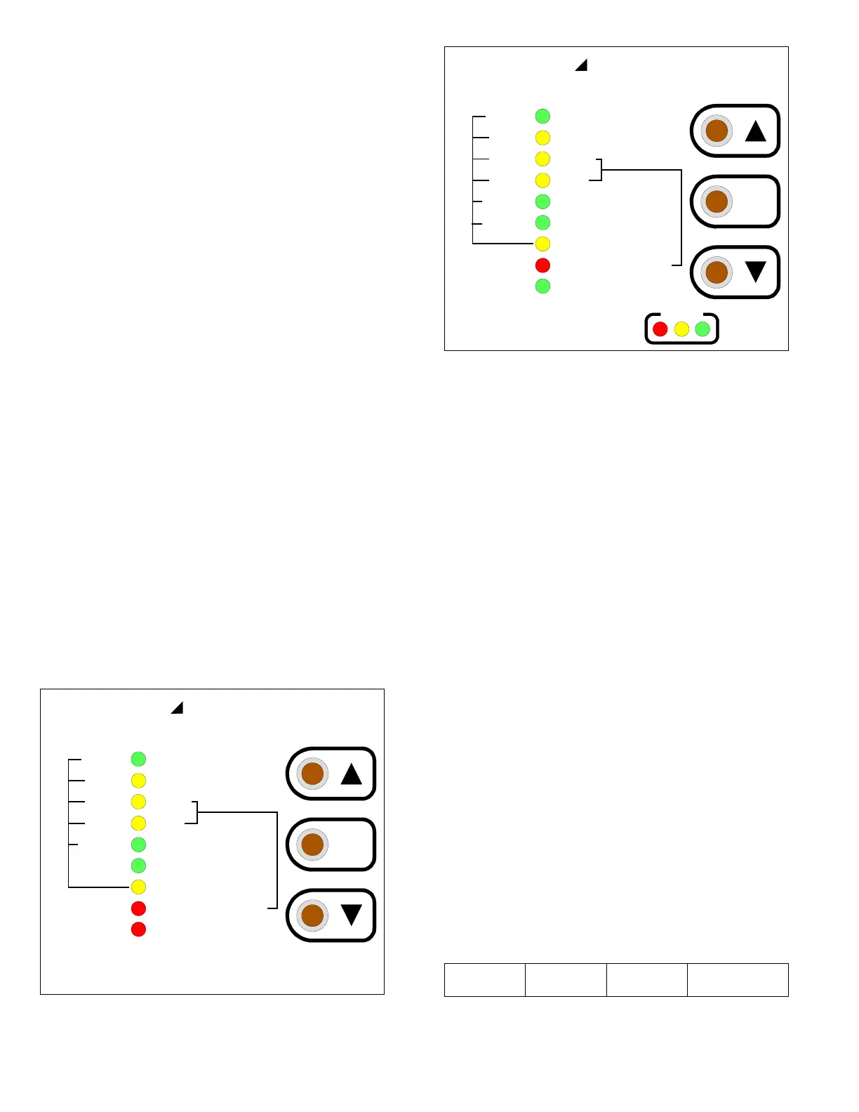
DHC CONTROL PANEL
Many of the DHC parameters relate to functions
that are set from the DHC controller's front panel. These
functions are referenced in the various discussions of the
digital parameters. Figures 1 and 2 provide a visual aid of
the DHC control panel.
AUTO
MANUAL / FB POT CAL
CLOSE
OPEN
AUX CLOSE OUTPUT
AUX OPEN OUTPUT
COMMAND TYPE
LOSS OF COMMAND
DIGITAL
4-20mA
1-5VDC
0-5VDC
0-10VDC
LAST
MODE
Digital High Resolution
AUX POSITION OUTFAULT
(FLASHING)
CAL (STEADY ON)
(BOTH OFF)
PEAKTRONICS
Figure 1 - DHC-100/200/300 Control Panel
AUTO
MANUAL / FB POT CAL
CLOSE
OPEN
AUX CLOSE OUTPUT
AUX OPEN OUTPUT
COMMAND TYPE
LOSS OF COMMAND
DIGITAL
4-20mA
1-5VDC
0-5VDC
0-10VDC
LAST
MODE
Digital High Resolution
(BOTH OFF)
PEAKTRONICS
POSITION OUT CAL
FAULT
2-10VDC
Figure 2 - DHC-400 Control Panel
CONTROL HIERARCHY
All DHC parameters can be monitored, or read, any
time the DHC is powered and on line. Reading parameters
does not interfere with the DHC's operation or settings.
Some parameters can be changed, or written, via the bus;
these are referred to as Read/Write Parameters. The DHC
will prohibit writing of various parameters to protect
against accidental interference with critical DHC functions
or settings; these are referred to as Read Only Parameters.
The DHC controller has a number of modes of
operation. With the exception of the AUTO mode, all the
modes are intended for either setup or trouble shooting
tasks. In those cases, it usually means that a human
operator has decided to control the actuator at the actuator
site. To prevent confusion, or even a hazard, to the human
operator, the DHC will ignore read/write parameters from
the bus that run the actuator. The automation system can
continue reading or writing such parameters, but the DHC
will not act on those parameters until the DHC is returned
to the AUTO mode. Section III discusses these parameters
in detail.
MODBUS to PACS
®
FORMAT
To convert the Modbus protocol to PACS
®
commands, the OCM-101 employs the user defined
Function Code $41 (65 decimal). The requesting Modbus
Application Data Unit (ADU) is shown below:
Address
Function
($41)
PACS
®
command
CRC or LRC