1. Antenna Input Connector A
2. Power Switch and Indicator:
When the switch is turned on the red indicator
illuminates to denote normal power status.
3. RF Signal Level Indicator:
Indicates the RF signal strength received from the
microphone. As soon as the signal is emitted from
the microphone the LED indicator illuminates.
4. Audio Signal Level Indicator:
Indicates the audio signal level. As soon as the
microphone signal is modulated, the LED indicator
illuminates.
5. Volume Control:
Adjusts the AF output level of the receiver.
6. Antenna Input Connector B
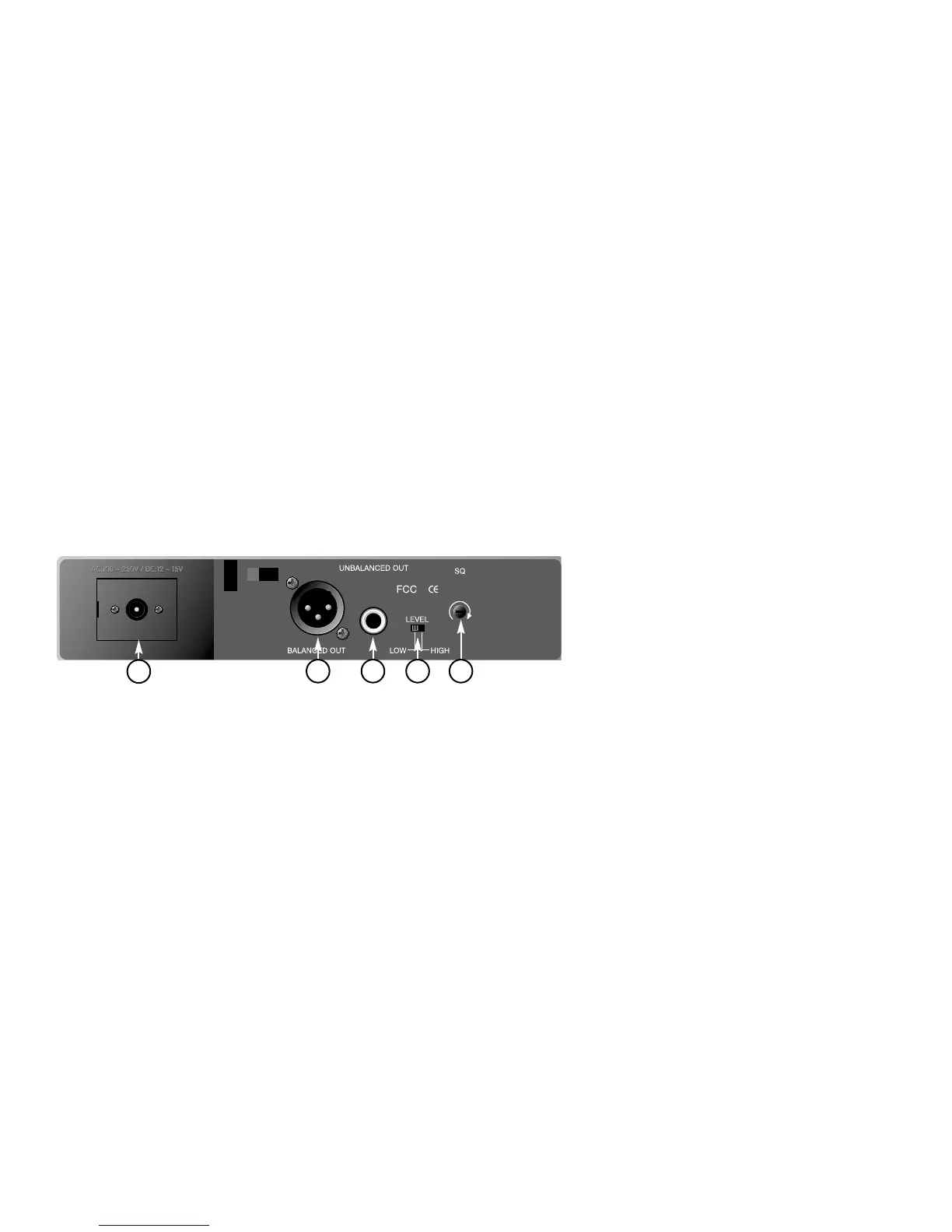
B. Rear Panel
7
8 9 10 11
Figure 2
4
 Loading...