g. Inspect shaft sleeves (14) for excessive wear.
h. Inspect bearings per Table I.
2-2. REPAIR. Make needed repairs in the following
manner:
a. If ID of casing ring (7, 7A) is grooved, scored or
eccentric, bore to produce a smooth, concentric surface.
Do not bore casing ring more than 1/8 inch larger than
original ID. If larger bore is required to produce a smooth
surface, replacement of casing ring and impeller ring is
recommended. Measure and record the new ID.
b. If impeller rings are defective, or mating casing rings
require boring, remove the old rings by turning in a lathe
– be sure machining is concentric with impeller ID. Use
care NOT to reduce hub OD.
NOTE
For bronze impellers and rings, the ring is shrunk on the
hub according to standard fit FN-4 of ANSI B4.1
standards.
For pumps of 10-inch discharge and larger, the rings are
also tack welded to the hub at 3 places 120 degrees apart.
Hardened impeller rings are installed according to ANSI
B4.1 standard fit FN-1.
c. Install new ring son the impeller (shrink or press
depending on material) and tack weld if old rings were
tacked. The ID is factory-machined for proper fit.
d. Turn the OD of the new rings to provide the proper
diametrical clearance and to be smooth and concentric
with hub bore. Use clearance limit from Figure 5, and ID of
casing ring from paragraph 2-2 a. to compute OD of
impeller rings.
e. Replace worn shaft sleeves.
f. Straighten or replace shafts having excessive run-out
(eccentricity).
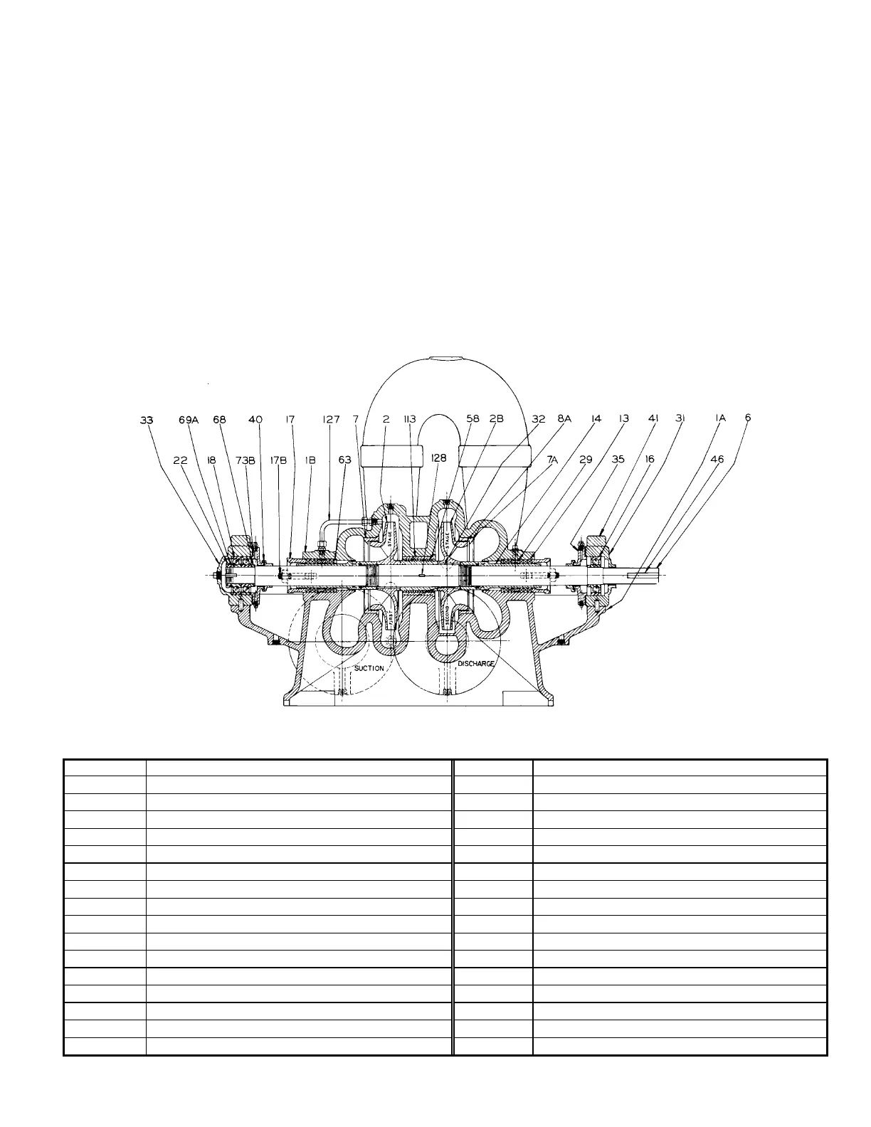
Figure 1 TYPE TU TUF-2 STAGE PUMPS WITH INTERNAL OR EXTERNAL CROSS-OVER GREASE LUBRICATED
BEARINGS
Parts List
Item No. Description Item No. Description
1A Lower Casing 32 Impeller Key
1B Upper Casing 33 Outboard Bearing Housing
2 Right Hand Impeller 35 Bearing Cover
2A Left Hand Impeller 40 Water Deflector
6 Shaft 41 Bearing Cap
7 Right Hand Casing Ring 46 Coupling Key
7A Left Hand Casing Ring 58 Inter-stage Sleeve
13 Packing 63 Stuffing Box Bushing
14 Shaft Sleeve 68 Shaft Collar
16 Outboard Bearing 69A Bearing Lock washer
17 Packing Gland 73A Casing Gasket (Not Shown)
17B Gland Bolt 73B Bearing Cover Gasket
18 Outboard Bearing 113 Inter-stage Bushing
22 Bearing Locknut 127 Seal Piping
29 Lantern Ring 128 Inter-stage Sleeve Key
31 Inboard Bearing Housing 130 Shaft Sleeve “O”-Ring
3
2883820