3
E. PLANNING THE LAYOUT
1. Prepare sketches and notes showing the layout of the
boiler installation to minimize the possibility of
interferences with new or existing equipment, piping,
venting and wiring.
2. Review the following sections of this manual for
consideration of the limitations with respect to:
a) Venting: Section 3
b) Air Intake Piping: Section 3
c) Condensate Removal: Section 3
d) Water Piping: Section 4
e) Oil Burner & Fuel Piping: Section 5
f) Electric and Controls: Section 6
PREINSTALLATION
This appliance is certified as an indoor appliance. Do
not install this boiler outdoors or locate where it will
be exposed to freezing temperatures.
WARNING
Do not install this boiler where gasoline or other
flammable liquids or vapors are stored or are in use.
WARNING
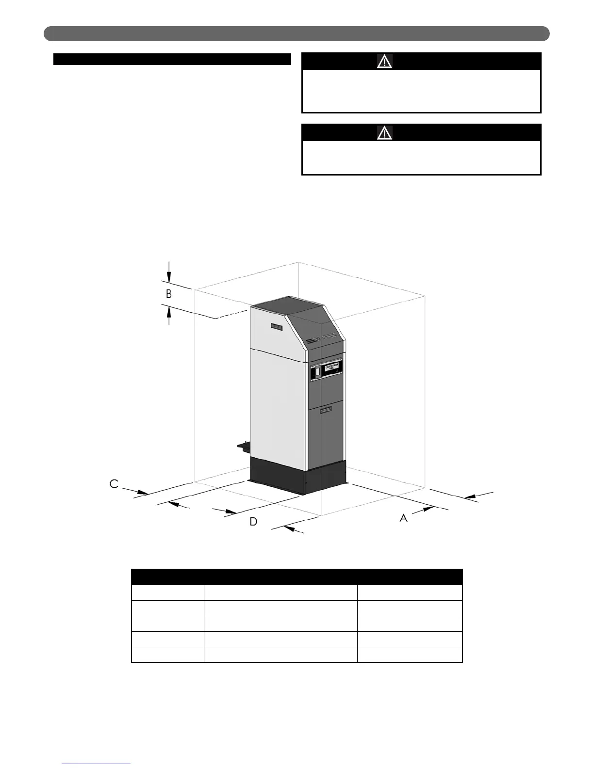
Service Clearances
Designation Description Dimension
“A” Burner Swing Clearance (Left or Right) 16" [406 mm]
“B” Jet/Acoustic Shroud Removal Clearance 13" [330 mm]
“C” Vent/Air Intake Sampling Clearance 12" [305 mm]
“D” Control Panel Access Clearance 24" [610 mm]
Figure 1.1: Recommended Service Clearances
 Loading...