OBTAINING THE BEST MEASUREMENT
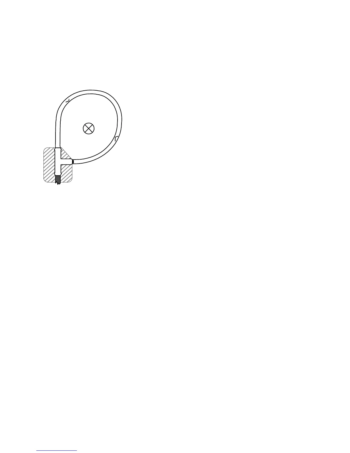
The Rogowski coil should be positioned so that the conductor under test is encircled by the coil but is
not adjacent to the cable attachment (see picture below). The arrows across the coil show the
direction a positive current should pass through the coil loop in order to obtain a positive output
voltage. The CWT has been calibrated with the conductor near the centre, and this is the ideal
position.
The sensitivity of the CWT to currents that do not pass through the coil is very small, provided that
such currents are no greater than the CWT’s rating or such currents are relatively distant from the
coil. In the vicinity of a multi-turn inductor the „H‟ field is far stronger than from a single conductor
carrying the same current, and such positions should be avoided.
Similarly if there is a surface with a high voltage very close to the coil, and the voltage is subject to
high rates of change (e.g. several 100 V/µs) or high frequency oscillations in the MHz range, then
measurement error can arise due to capacitive coupling to the coil.
As a check on any unwanted response to adjacent fields, it is wise to display the output of the CWT
when close to (but not encircling) the conductor whose current is to be measured. This will reveal the
magnitude of any unwanted response to currents close to but outside the coil.
EMC
EMISSIONS
PEM‟s Rogowski current waveform transducers are certified to: BS EN 50081-2:1994
IMMUNITY
PEM‟s Rogowski current waveform transducers are certified to: BS EN 50082-2:1995
OUTPUT CABLES
A 0.5m BNC-BNC output cable is supplied with the unit but a longer cable can be used. The cable
should be a 50 ohm singly screened co-axial cable. Although at present this has not been included in
the immunity tests and may decrease RF noise immunity, PEM does not consider the use of
extension cables to be problematic from the noise viewpoint. PEM has conducted tests using a 25m
extension and no discernible attenuation of measured current signal has occurred although, as is to
be expected, there is an increased measurement delay of 5ns/m.
 Loading...