4 A19BAC, A28AA Installation Instructions
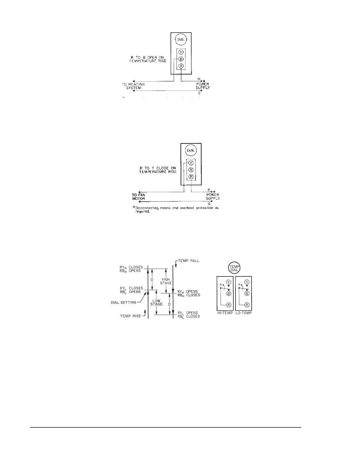
Fig. 5 – A19BAC typical ventilating or cooling control
circuit.
Fig. 6 – Switch action of the A28AA two-stage control.
, RY
H
indicate HI-TEMP. RB
L
, RY
L
indicate LO-TEMP. D
is the differential between stages.
*Disconnecting means and overload protection as required.
Fig. 4 – A19BAC typical heating control circuit.
RB
H