www.penncontrols.com
® Johnson Controls and Penn are registered trademarks of Johnson Controls in the United States of America and/or other countries. All other trademarks used herein are the property of their respective owners.
© Copyright 2022 by Johnson Controls.
All rights reserved.
Mounting for direct duct with L
bracket No. BKT182-2R where inside
of duct is not accessible for securing
lock nut. See Fig. 3.
1. Cut or drill a 1 1/4 in. (32 mm) diameter hole
in duct.
2. Secure mounting bracket to switch with angle
at side of switch using 1/2 in. conduit lock
nut.
3. Mount to duct using sheet metal screws
through the four holes in large surface of
mounting bracket.
Mounting for direct mounting with
channel U bracket No. BKT229-1R. See
Fig. 4.
1. Drill a 1/4 in. (6 mm) hole in the duct at
sensing location.
2. Install 1/4 in. tube into metal (high pressure)
connector with compression fitting and
coupling.
3. Secure bracket to switch with 1/2 in. conduit
lock nut, if not factory installed.
4. Remove adhesive protection paper from
gasket and slide gasket onto 1/4 in. tube with
adhesive away from switch.
5. Place switch on duct tube in 1/4 in. hole, drill
or punch mounting screw holes.
6. Fasten to duct with the two self-tapping
screws.
7. Press gasket against duct.
Mounting for remote. See Fig. 5.
1. If direct panel mount is required, drill 7/8 in.
(22 mm) diameter hole and secure with lock
nut.
2. When mounting bracket is required, use L
bracket No. BKT182-2R.
3. Use the bracket as a guide and drill or punch
the mounting screw holes.
4. Determine the correct mounting bracket
position and secure it to the switch with
1/2 in. conduit lock nut. There may be
installations where the bracket must be
installed before fastening it to the switch.
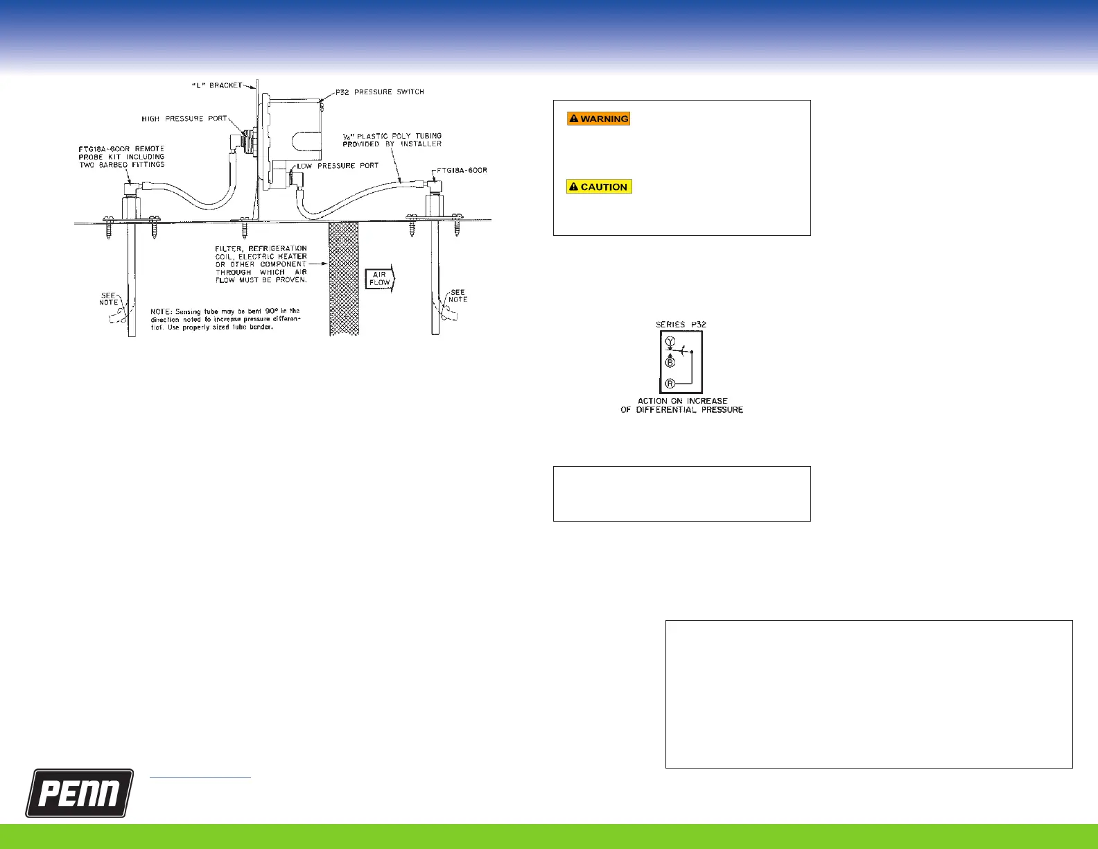
5. Use FTG18A-600R remote mounting probe
kits for remote sensing locations. Run plastic
or copper tubing from the high and/or low
pressure connectors to the sensing point. Use
tubing with at least .17in. I.D. (1/4in. O.D.)
Figure 5: The P32 may be mounted on either a vertical or horizontal surface
using an L bracket and two FTG18A-600R remote mounted probe kits.
Wiring
Risk of electrical shock.
Disconnect the electrical power
supply before wiring the switch into circuit to
avoid electrical shock.
Risk of equipment damage.
Disconnect the electrical power
supply before wiring the switch into circuit to
avoid possible damage to equipment.
Make all wiring connections using copper
conductors only, and in accordance with the local,
national, and regional regulations.
Figure 6: Switch action on the P32 control.
Important: Use terminal screws furnished (8-
32 x 1/4in. binder head). Substitution of other
screws may cause problems in making proper
connections.
The single pole double throw (SPDT) models have
color coded terminals. The Red to Yellow circuit
closes on differential pressure increase and the red
to blue circuit opens. See Fig. 6.
Adjustment
The field-adjustable switch has an adjusting screw
located under the cover. Some models have a
scale plate for adjusting convenience.
To adjust, complete the following steps:
1. Remove cover.
2. Turn adjusting screw CW to increase the
differential pressure setpoint.
3. Turn adjusting screw CCW to decrease the
setpoint.
4. If the high or low adjustment stop is reached,
back off the adjusting screw at least 1/6 turn
from the stop.
Checkout procedure
Before leaving the installation, observe at least
three complete operating cycles to ensure that all
components function correctly.
Repairs and replacement
Field repairs must not be made. For a replacement
pressure switch, contact the nearest Johnson
Controls distributor.
APAC Single Point of Contact:
JOHNSON CONTROLS
C/O CONTROLS PRODUCT MANAGEMENT
NO. 32 CHANGJIANG RD NEW DISTRICT
WUXI JIANGSU PROVINCE 214028
CHINA
European Single Point of Contact:
JOHNSON CONTROLS
VOLTAWEG 20
6101 XK ECHT
THE NETHERLANDS
NA/SA Single Point of Contact:
JOHNSON CONTROLS
5757 N GREEN BAY AVE.
GLENDALE, WI 53209
USA
UK Single Point of Contact:
JOHNSON CONTROLS
TYCO PARK
GRIMSHAW LANE
MANCHESTER M40 2WL
UNITED KINGDOM
 Loading...