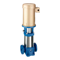
VERTICAL MULTISTAGE PUMPS
13
TWO PART MECHANICAL SEAL/DISASSEMBLY. See
Table VII to determine which seal your model has.
TABLE VII – Seal Type Identification
2 Part
Low Pressure Seal
7 Part
High Pressure Seal
B78038 B78039
PVM2-30/2 through PVM2-120
PVM4-20/2 through PVM4-120
PVM2-150, PVM2-180
PVM4-140, PVM4-160
B78040 B78041
PVM8-20/1 through PVM8-120
PVM16-30/2 through PVM16-80
PVM8-140, PVM8-160
PVM16-100, PVM16-120
See Figures 14 and 15 for reference numbers.
NOTICE: The assembly and disassembly procedure for this seal
does not require extraordinary force.
1. Follow steps 1–8 under Motor Replacement and proceed
with step 2 below.
2. Remove the four nuts, lockwashers, and washers (8, 9A, and
9B) from the staybolts (19).
3. The shaft seal consists of a stationary half (14A) and a
rotating half (14B). Turn the motor bracket upside down and
remove the stationary part of the seal (14B) from the seal
seat in the base of the motor bracket.
NOTICE: Use care not to chip or scratch the seal seat
during disassembly and assembly.
4. Clean the seal seat with a wet cloth.
5. Remove and discard the rotating parts of the seal by twisting
and pulling up on them until they come off the shaft.
TWO PART MECHANICAL SEAL REASSEMBLY.
NOTICE: Before assembly check and clean all sealing and
gasket surfaces with a clean wet cloth. Replace all seals, gaskets
and O-rings.
1. Turn the motor bracket upside down.
2. Moisten the seal seat (in the motor bracket) and the O-ring
(cup seal) portion of the stationary half of the mechanical
seal (14A) with a small amount of water.
3. Press the cup-seal onto the stationary half of the shaft seal
and then press the shaft seal into the seal seat of the pump
head (cup-seal portion first), using finger pressure only.
NOTICE: If a tool is used, protect the seal face from tool
with a clean cloth.
NOTICE: The cup-seal must be placed evenly on the seal
and the seal must be installed evenly in the seal seat to avoid
pinching the cup-seal.
4. Moisten the internal parts of the rotating portion of the
mechanical seal (14B).
5. Install the rotating half of the seal onto the shaft. Push and
twist the seal onto the shaft to the stop ring.
NOTICE: Use care when installing the new seal on the
shaft. Do not scratch or mar seal on the shaft shoulder.
6. Follow steps 11–23 under Replacing Pump Stack.
SEVEN PART MECHANICAL SEAL/DISASSEMBLY. See
Figures 14 and 15 for reference numbers.
1. Follow steps 1–8 under Motor Replacement and proceed
with step 2 below.
2. Remove the four nuts, lockwashers, and washers (8, 9A and
9B) from the staybolts (19).
3. The shaft seal consists of an O-ring (15A), the stationary
half of the mechanical seal (15B), the rotating half of the
mechanical seal (15C), a second O-ring (15D – inside 15C),
a flat washer (15E), a spring (15F), and a mechanical drive
ring (15G), in that order; see Figure 13. Turn the pump head
upside down and remove the stationary part of the seal (15B)
from the seal seat in the base of the motor bracket.
NOTICE: Use care not to chip or scratch the seal seat
during disassembly and assembly.
Warning: Hazardous Voltage
Can shock, burn, or cause death. Disconnect power to pump
before disassembly.
Warning: Hazardous Voltage
Can shock, burn, or cause death. Disconnect power to pump
before disassembly.
15A
15B
15C
15D
15E
15F
15G
16A
16B
16C
16A
Figure 13.

 Loading...


