3
seal cham ber are com pletely sealed
with O-rings located at mating part
faces.
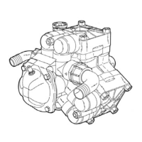
The power cord entry system is
designed to give double seal ing.
The chamfered pilot of the motor
housing mates with the molded
cord end to form the first seal. The
cord grip forms the second seal
around the molded cord end and
provides strain relief. The ca ble
on the HPG model includes the
leads for both heat sensors (motor
protection) and the seal sen sor lead
for seal leakage de tec tion.
The cutters are designed to be self
adjusting and will not need to be
shimmed or reset.
Application:
These pumps are designed for
either residential or industrial
sew age discharge ap pli ca tions
with a pH ranging from 5 to 9,
spe cif ic gravities from 0.9 to 1.1,
viscosities ranging from 28 to 35
S.S.U., and tem per a tures up to
140°F.
Codes:
All local wiring codes must
be observed. Consult the local
inspector before in stal la tion to
avoid costly delays that can
occur due to rejection after job
is finished.
Pump Installation
Unpacking Pump:
Remove pump from carton. When
un pack ing unit, check for
con cealed damage. Claims for
damage must be made at the
receiving end through the delivery
carrier. Dam age cannot be
processed from the factory.
Location:
If pumps are installed in an
existing basin or concrete sump,
the piping can either be connected
permanently or rails and brackets
ELECTRICAL CONNECTIONS
1 Phase 3 Phase
Green Ground Ground
Red Start Power Line Power Line
White Main Power Line Power Line
Black Common Power Line Power Line
Orange Seal Failure Seal Failure
Blue Heat Sensor Heat Sensor
White Heat Sensor Heat Sensor
w/ black
stripe
WHITE W/BLACK STRIPE - P1
BLUE - P2
ORANGE - SEAL PROBE
SENSOR LEADS
208 - 230V SINGLE PHASE
T4
(WHITE) (BLACK) (RED)
T5 T8
BLACK
L2
WHITE
L1
RED
L3
P1 (PURPLE)
P2 (BROWN)
MOTOR LEADS
230V (DUAL VOLTAGE) THREE PHASE
P1 (PURPLE)
P2 (DARK BROWN)
T7
(PINK) (RED) (LT. BROWN)
(BLUE) (TAN) (ORANGE)
T8 T9
T1 T2 T3
T4
(YELLOW) (BLACK) (LAVENDER)
T5 T6
BLACK
L2
WHITE
L1
RED
L3
200V AND 575V THREE PHASE
T1
(BLUE) (TAN) (ORANGE)
T2 T3
BLACK
L2
WHITE
L1
RED
L3
P1 (PURPLE)
P2 (BROWN)
460V (DUAL VOLTAGE) THREE PHASE
PL (PURPLE)
P2 (DARK BROWN)
T7
(PINK)
(RED)
(LT. BROWN)
(BLUE) (TAN) (ORANGE)
T8 T9
T1 T2 T3
T4
(YELLOW) (BLACK) (LAVENDER)
T5 T6
BLACK
L2
WHITE
L1
RED
L3
Pump Operations
To reduce the risk of electrical
shock, install only on a GFCI
protected circuit. See pump
nameplate for electrical ratings.
To start the pump, perform the
following steps in order:
1. When grinder pump is single
phase, no rotation check
is necessary. Correct rotation is
counter-clockwise.
2. Run water into sump until
motor is covered.
3. Open gate valve in discharge
line.
4. Turn pump on. If pump runs
and sump liquid does not pump
down, stop pump and close
discharge gate valve. Lift pump
until sealing ange is open to
vent off trapped air. Lower
pump, open discharge valve,
and start the pump again.
CAUTION: Positive displacement
pump is designed to operate at
minimum 5 GPM capacity. Running
pump at shut-off condition or with
gate valve closed can result in
damage to the pumping stator boot
and rotor.
5. Level control should be set so
that pump turns off when level
is about 2 inches above inlet
of pump suction and turns on
when level is about 2 inches
above motor.
can be fur nished for mounting to
walls of basin. In either case, be
sure that the Hydromatic
®
solids
handling check valve is used and
that the pumps are submerged in
a vertical position. The complete
factory built packaged system
is recommended for the most
satisfactory installation and
generally for the low est cost where
expensive instal la tion labor is
involved.
Electrical Connections:
Make all connections from motor to
control panel to com ply with local
codes.
CAUTION: Make sure that
the ground wire is securely
connected and that the unit
is properly grounded in
accordance with local codes.
 Loading...