5
Junction Box:
If a junction box is used in a
hazardous location, it must
follow national and local codes
for placement inside a hazardous
area.
Level Sensing Controls:
Intrinsically safe-type float
controls are recommended for
all applications and required for
hazardous location service. An
intrinsically safe control panel
relay will limit the current and
voltage to the level controls. A
Hydromatic control panel can be
supplied with this type circuitry.
The float level controls maintain
the basin sewage water level by
controlling pump turn-on and
turn-off levels.
1. The lower turn-off control
should be set so that the pump
stops with the water covering
the entire motor housing.
Consult the factory for any
settings below this point.
2. The upper turn-on control
should be set above the
lower turn-off control. The
exact height between the two
controls is determined by the
number of pump starts desired
and the depth of the basin.
A maximum of 10 starts per
hour should not be exceeded.
3. The override control is set at
a specified height above the
upper turn-on control.
4. The alarm control is set about
6" to 12" above the override
control.
5. No control should be set above
the inlet invert.
Electrical Connections:
All electrical wiring must be in
accordance with local code and
only qualified electricians should
make the installations. Complete
wiring diagrams are included for
use in making the installation. All
wires should be checked for shorts
to ground with an ohmmeter or
Megger after the connections are
made. This is important, as one
grounded wire can cause failure
of the pump, control panel or
personal injury.
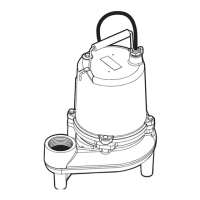
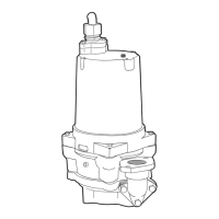
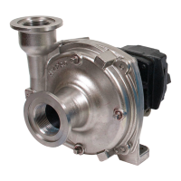
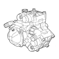
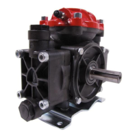
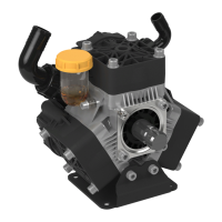
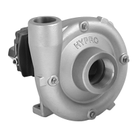
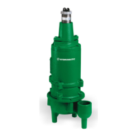
Pump:
The fluid end of the pump is
field serviceable and can be
disassembled in case of wear,
damage, plugging or outboard
seal failure. The following will
describe the disassembly and
reassembly process.
WARNING: Disconnect the
power first.
Disassembly:
1. With the pump located in a
secure place, remove the bolts
fastening the seal housing to
the volute. The motor and
impeller can now be removed
as a unit.
2. Lay the unit down on its
side. If the lower seal is to be
removed, it is recommended
that the oil in the seal chamber
be drained. This can be done
by removing the lower seal
chamber plug and draining the
oil into a holding container.
3. Using a proper wrench, the
impeller retaining nut must be
removed. This may require a
piece of wood placed between
the vanes to keep the impeller
from rotating while removing
the nut. Loctite
™
is used on
this bolt and heating to 450°F
to 500°F may also be required
to loosen. The impeller is
mounted on a threaded shaft.
To remove impeller, rotate
impeller with one hand while
holding pump shaft with
screwdriver.
4. If the lower seal needs to
be removed, first remove
the compression spring that
rides between the impeller
and the seal assembly. Next
take a pair of screwdrivers
and remove the compression
ring that surrounds the rubber
bellows on the rotating portion
of the seal assembly. Again
using the screwdrivers, pry
the remaining portion of the
rotating seal assembly off the
shaft. The ceramic stationary
assembly can be removed by
placing a screwdriver between
the rubber and the ceramic
face, and then prying, working
around the entire diameter.
Note, these parts should be
discarded and a new seal
assembly installed.
5. If the oil in the seal chamber
was drained, examine the
contents to determine if the
upper seal has been damaged.
Signs of grit or other abrasive
material may indicate that
the upper seal has also been
damaged. Pressurizing the
motor housing assembly
between 7 and 10 psi and
observing any drop in pressure
will indicate if the upper seal
is functioning properly.
NOTE: Upper seal repairs
must be done at a Hydromatic
authorized service center or at
the Hydromatic factory. Any
unauthorized field repair voids
warranty and the hazardous
location approval on the CSA
listed pumps.
Reassembly:
1. Remove the ceramic portion
of the new seal from the
package. Brush new dielectric
oil around the rubber portion
of the stationary assembly
and into the pocket in the
seal housing. Note, keep the
 Loading...