6
vent hole is clean after any
service work on pump. Air
venting is not a problem after
initial start.
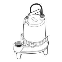
Pump
Troubleshooting
Checking for Moisture
in Motor:
Use an ohmmeter or a Megger and
set on highest scale. Readings
on the large power cord between
any of the conductors red, black
or white to the green conductor
or to the motor housing should
be greater than 1,000,000 ohms
(megohm).
A motor will probably run with a
lower reading, but if the pump is
out of service and the value of the
reading is below 1,000,000 ohms
(1 megohm), the motor housing
and stator should be re moved and
baked in a drying oven at 220°F.
This service work must be done
only at an authorized service
station.
NOTE: Readings should
be taken with the line leads
disconnected from the control
panel.
Below is a list of troubles and
their probable causes:
Red light comes on at
control box.
This indicates some water has
leaked past the lower seal and
has entered the seal chamber and
made contact with the elec trode
probe. Pump must be removed
for re place ment of lower seal.
This pre ven tive repair will save
an expensive motor.
Overload trips at control box
and alarm buzzer or flashing
red light comes on due to high
water level in basin.
1. Push in on red reset button to
reset overload. If overload
trips again after short run,
pump has some damage and
must be removed from basin
for check ing.
2. Trouble may be from clogged
impeller causing motor to
overload or could be from
failed motor.
3. Trouble may be from faulty
component in control box.
Always check control box
before removing pump.
Yellow run light stays on
continuously.
1. Indicates H-O-A switch may
be in the Hand position.
2. Level control switch may
have failed, causing pump
to continue to operate when
water is below lower control.
3. Impeller may be partially
clogged, causing pump to
operate at very reduced
capacity.
4. Gate valve or check valve may
be clogged, causing low pump
flow.
5. Pump may be air logged.
Circuit breaker trips.
1. Reset breaker by pushing
completely down on handle
oil off the seal face. Without
scratching the seal face, press
the ceramic stationary portion
into the seal housing. Seal
installation tool can be ordered
from Hydromatic. With clean
cloth, lightly wipe the face
of the seal surface to make
sure it is dirt free. Remove
the rotating portion of the
seal from the package and
lubricate the inside diameter
of the rubber bellows and the
outside diameter of the shaft.
Place the seal over the shaft
with the seal installation tool.
Evenly press on the body of
the rotational assembly and
slide it down the shaft until the
seal faces meet. Once the seal
assembly is in position, place
the spring over the register on
the rotational portion of the
seal.
2. Thread the impeller onto
the shaft, making sure that
the seal spring is registered
properly onto the back side of
the impeller. Place the proper
Loctite fluid on the impeller
retaining nut. Tighten nut on
shaft.
3. Fill the seal chamber with
new dielectric oil. An air
gap of 10–15% volume must
be left for the expansion of
the oil when it is at operating
temperature.
4. The motor and impeller
assembly can be installed into
the volute, making sure that
the units are aligned properly.
Install the volute retaining
bolts and tighten.
5. Air tends to trap in the pump
case when water rises in the
sump or when the pump is
lowered into the water after
service. To vent off this air,
a small hole is drilled into the
volute casting. Be sure this
PROBE TEST RESISTOR
ON HAZARDOUS LOCATION ONLY
 Loading...