9
Reassembly Instructions
Fig. 19
Fig. 20
Fig. 21
Fig. 22
REASSEMBLY:
1. Insert a shim between the impeller vanes and pump wear plate. A shim 1/2”
wide and 0.040” to 0.050” is required. Plastic or steel banding can be used as
a shim. Verify banding thickness prior to use. Place shim material into the pump
through the outlet port. Shim material must lie across the wear plate. (Figure
19)
Note: Use caution not to damage ceramic and carbon seal faces while
installing impeller assembly and adapter flange onto pump.
2. Install impeller assembly, ensuring the impeller vanes rest on the shim material.
3. Install new gasket onto pump over mounting studs. Gasket sealant is not
required.
4. Install adapter flange over mounting studs.
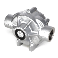
5. Tighten (6) nuts and lock washers. (Figure 20)
A. 2” pump – 5/16 x 18 nut – 11 ft.-lbs./ 14.9 Nm torque.
B. 3” pump – 3/8 x 16 nut – 20 ft.-lbs./ 27.1 Nm torque.
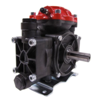
6. Install two-bolt clamp over drive sleeve. Be careful to ensure keyed
portion of clamp sits in drive sleeve slot. Leave bolts and nuts finger tight.
***Some clamps may not have an integral key. (Figure 21)
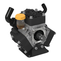
7. Apply an anti-seize compound to engine, motor, or pedestal shaft.
8. Install gas engine, c-faced electric motor, or pedestal into pump drive sleeve.
Align keyway of drive source with slot in drive sleeve. Do not rotate the pump
shaft during assembly. This may cause the shim to become dislodged.
9. Install (4) mounting bolts between pump adapter and gas engine, electric motor,
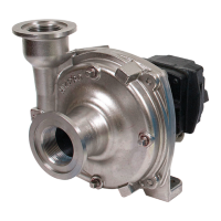
or pedestal. (Figure 22)
A. 2” pump – 5/16 x 24 screw – 11 ft.-lbs./ 14.9 Nm torque.
B. 3” pump – 3/8 x 16 screw – 20 ft.-lbs./ 27.1 Nm torque.
10. Alternately tighten clamp bolts to ensure even torque and balance.
A. 2” pump – 5/16 x 18 screw – 20 ft.-lbs./ 27.1 Nm torque.
B. 3” pump – 3/8 x 16 screw – 40 ft.-lbs./ 54.2 Nm torque.
11. Remove shim stock from pump outlet.
12. Pump and drive source should rotate freely.

 Loading...