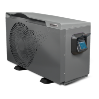
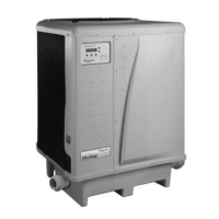
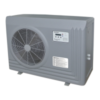
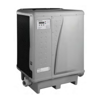
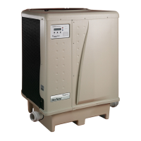
The document provided is an installation and operating manual for the Pentair InverTemp®-FL full inverter swimming pool heat pump (HP). This device is designed to heat swimming pool water efficiently and is available in several models: IVTP-1M-FL, IVTP-2M-FL, IVTP-3M-FL, IVTP-4M-FL, IVTP-5M-FL, and IVTP-6M-FL.
Function Description
The Pentair InverTemp®-FL heat pump is a full inverter system designed to heat swimming pool water. It operates by extracting heat from the ambient air and transferring it to the pool water. The "full inverter" technology allows the compressor and fan motor to adjust their speed continuously, optimizing heating capacity and energy consumption based on the specific needs of the pool and ambient conditions. This results in higher efficiency and quieter operation compared to traditional on/off heat pumps. The device uses R32 refrigerant, which is a category A2L coolant with low combustion speed and a global warming potential (GWP) of 675, making it a more environmentally friendly option compared to older refrigerants. The HP is designed for outdoor installation and must be integrated into the pool's hydraulic circuit after the filter and before any chemical treatment systems. It can be controlled via an electronic control unit with a display, offering various operating modes and settings.
Important Technical Specifications
The heat pumps operate on a 230 V ~, 50 Hz power supply and have an IP:X4 rating, indicating protection against splashing water. They are designed for an operating temperature range of -15°C to 38°C and a maximum operating altitude of 2000 m.
Heating Capacity and COP (Coefficient of Performance) at different conditions:
-
Dry air temperature: 28°C, Relative humidity: 80%, Input water temperature: 28°C
- IVTP-1M-FL: Heating capacity (Boost Mode) 6.8 kW, COP (Boost Mode) 5.9-6.5. Max power consumption 1.6 kW, Weight 40 kg.
- IVTP-2M-FL: Heating capacity (Boost Mode) 8.8 kW, COP (Boost Mode) 5.5-6.5. Max power consumption 1.7 kW, Weight 40 kg.
- IVTP-3M-FL: Heating capacity (Boost Mode) 10.6 kW, COP (Boost Mode) 5.4-6.8. Max power consumption 2.0 kW, Weight 46 kg.
- IVTP-4M-FL: Heating capacity (Boost Mode) 12.8 kW, COP (Boost Mode) 5.6-6.8. Max power consumption 2.7 kW, Weight 46 kg.
- IVTP-5M-FL: Heating capacity (Boost Mode) 16.5 kW, COP (Boost Mode) 5.1-6. Max power consumption 3.1 kW, Weight 57.5 kg.
- IVTP-6M-FL: Heating capacity (Boost Mode) 20.1 kW, COP (Boost Mode) 5.2-5.9. Max power consumption 3.7 kW, Weight 65.5 kg.
- Smart and Eco modes offer lower heating capacities with higher COP values, indicating better energy efficiency. For example, IVTP-1M-FL in Smart mode has a heating capacity of 3.2-6.8 kW and COP of 5.9-10.8, while in Eco mode, it has 3.2-5.8 kW and COP of 8.3-10.8.
-
Dry air temperature: 15°C, Relative humidity: 70%, Input water temperature: 28°C
- Heating capacities range from 5.4 kW (IVTP-1M-FL) to 14.6 kW (IVTP-6M-FL) in Boost mode.
- COP values are generally lower than at 28°C ambient temperature, reflecting reduced efficiency in cooler conditions.
-
Dry air temperature: 7°C, Relative humidity: 0%, Input water temperature: 26°C
- Heating capacities range from 2.75 kW (IVTP-1M-FL) to 8.3 kW (IVTP-6M-FL).
- COP values are further reduced, e.g., 2.86 for IVTP-1M-FL and 3 for IVTP-6M-FL.
Sound Pressure at 10m: Ranges from 22-32 dB(a) for IVTP-1M-FL to 29-40 dB(a) for IVTP-6M-FL, indicating relatively quiet operation.
Components:
- Compressor: Mitsubishi / Toshiba 2D Full DC Inverter
- Expansion valve: Electronic
- Cabinet: Painted sheet metal - Reinforced ABS, UV protection, and equipped with soundproof panels.
- Refrigerant: R32 (recyclable, no impact on ozone layer).
Hydraulic Connection: 1.5" / 50 mm PVC piping.
Minimum Water Flow: 4 m³/h for IVTP-1M/2M/3M/4M-FL, 5 m³/h for IVTP-5M-FL, and 6 m³/h for IVTP-6M-FL.
Electrical Connection:
- Fuse rating: C 10 A (IVTP-1M/2M/3M-FL), C 16 A (IVTP-4M-FL), C 20 A (IVTP-5M/6M-FL).
- Power supply cross section: 3G 2.5 mm² (IVTP-1M/2M/3M/4M-FL), 3G 4 mm² (IVTP-5M/6M-FL).
- Maximum cable length varies with current and cross-section, e.g., for IVTP-1M-FL (4.9 A), 3x2.5 mm² for 34m, 3x4 mm² for 54m, 3x6 mm² for 80m, and 3x10 mm² for 135m.
- Magnetic-thermal protection (C): 10 A (IVTP-1M/2M/3M-FL), 16 A (IVTP-4M-FL), 20 A (IVTP-5M/6M-FL).
Usage Features
The heat pump offers several operating modes:
- Boost Mode: Provides maximum heating capacity for rapid temperature increase.
- Smart Mode: Balances heating capacity and energy efficiency.
- Eco Mode: Prioritizes energy savings with reduced heating capacity.
- Cooling Mode: Allows the HP to cool the pool water, if desired.
- Automatic Mode: The HP automatically selects the best mode based on the desired temperature and current conditions.
Electronic Control Unit (Regulation):
The device features an electronic control unit with a display for easy operation and monitoring.
- Home Screen: Shows current water temperature, selected mode, energy mode, timer status, Wi-Fi connection, and HP operating status (running/stopped).
- Settings: Allows users to adjust desired bathing temperature, set timers for operation, and configure other parameters.
- Information: Provides details like software release and production date.
- Error Codes: Displays a list of recent error codes for troubleshooting.
- Wi-Fi Connectivity: The HP can be connected to Wi-Fi for remote monitoring and control (details on specific app/platform not provided in this manual).
- Heating Priority: The HP can be connected to the filtration pump to force filtration when heating is required, ensuring the desired temperature is maintained. This requires a 230V AC dry contact relay.
Installation and Start-up:
- Site Selection: Must be installed outdoors, at least 2 meters from the pool, on a stable, level surface with vibration absorbers. Requires 1m (30cm minimum) open space behind/sides and 3m in front of the fan outlet.
- Hydraulic Connection: Connects to the pool's hydraulic circuit via Ø50mm PVC pipes. A bypass system must be installed to facilitate maintenance.
- Condensate Evacuation: The HP produces condensation, which must be channeled to a suitable evacuation circuit using the provided pack.
- Electrical Connection: Requires a dedicated power supply protected by a 30-mA differential switch and a suitable class C circuit-breaker.
- Start-up Procedure: Involves opening bypass valves, purging air from the water circuit, starting the filtration pump, powering up the HP, and adjusting temperature and water flow.
- Water Flow Setting: Crucial for optimal performance. Adjusted by opening or closing the bypass valve based on the pressure gauge reading, aiming for a temperature difference of 10-15°C between the HP outlet and pool water temperature.
Remote Control: The HP can be controlled via a dry contact (switch) or through the Pentair RS-485 bus, allowing integration with systems like Pentair IntelliPool or Speedeo.
Maintenance Features
General Use:
- Water Quality: Maintain chlorine concentration below 2.5 ppm and pH between 6.9 and 8. Isolate the HP during sudden chlorination.
- Maintaining Temperature: Once the desired temperature is reached, set daily filtration time (8-10 hours minimum) to allow the HP to operate as needed. Cover the pool to reduce heat losses.
Regular Maintenance (at least once yearly):
- Cleaning:
- Clean the inlet of the evaporators and the outlet of the fan to maintain yield.
- Clean the outer casing with a damp soft cloth; avoid detergents or household products.
- Clean the evaporator at the rear/sides of the HP carefully with a soft brush, vacuum cleaner, or stream of soft water (avoid high-pressure hoses).
- Safety Checks (by a qualified technician):
- Check electrical cables and earth terminals for proper connection.
- Check the pressure gauge and ensure it aligns with the temperature (refer to the provided table) and for coolant presence. This is critical as high pressure and temperature in the cooling circuit can cause severe burns.
- A search for leaks in the cooling circuit must be conducted at least once a year by a certified specialist.
Troubleshooting (Table of Different States of the Display):
The manual provides a table of display messages (e.g., "St-by" for Standby, "FLO" for No/insufficient water flow, "AL" codes for various errors) with corresponding meanings, verification steps, and required actions. For example, "FLO" indicates insufficient water flow, requiring a check of water flow, filter clogging, bypass setting, and water direction. Error codes like "AL3" (Sensor error, water inlet) require checking the sensor connection.
Wintering:
The manual outlines a procedure for wintering the HP:
- Turn off power supply.
- Fully open the bypass valve and close HP inlet/outlet valves.
- Unscrew junctions to evacuate all water from the HP.
- Reconnect and slightly tighten junctions to prevent foreign objects.
- Place the provided wintering blanket over the HP.
Recycling:
At the end of its lifespan, the HP must be brought to a selective recycling point. It contains potentially hazardous substances that must be eliminated or neutralized during recycling. Options include bringing it to a recycling center, a not-for-profit organization for repair/reuse, or the shop when buying a new unit.