15
KEYSTONE EPI-2 QUARTER-TURN ELECTRIC ACTUATOR
InstallatIon and MaIntenance InstructIons
FIGURE 12 - Removal of the control unit cover.
6.2 LOCAL CONFIGURATION OF THE EPI-2
6.2.1 EPI-2 default general configuration
If the application requires different actuator
configurations, please proceed as described in
this chapter.
The configuration of the actuator parameters is
done through the following tools:
• Two rotary selector switches SW6 and SW4
for actuator configuration
• Enter pushbutton SW5 (confirmation
pushbutton)
• Dip switch SW3 (enable configuration
function)
• Green LED indicating power ON (switched on
when power supply is available)
• Red LED for Enter confirmation (ON once
configuration is confirmed)
• Mechanical stops
WARNING
The configuration must be done while the
actuator is powered on. As a consequence, all
configuration operations must be carried out by
specifically qualified personnel for operations on
powered electronic cards.
IMPORTANT
The actuators are set in the workshop with the
following configuration (default value):
• CL limit switch by position
• OP limit switch by position
• Stroking time in CL (6): 28 secs for models
063/125/250/500, 45 secs for model 1000 and
100 secs for model 2000
• Stroking time in OP (6): 28 secs for models
063/125/250/500, 45 secs for model 1000 and
100 secs for model 2000
• Torque limiting device in CL set at about 100%
of nominal torque
• Torque limiting device in OP set at about 100%
of nominal torque
• Reverse mode off
• Monitor Relay NC (in normal condition, i.e.
without alarms)
• Blinker / Local Selector relay off (always Open)
IMPORTANT
Please note that the actuator configuration does
not need to be done in succession as indicated in
the following pages. Each parameter can be set
independently.
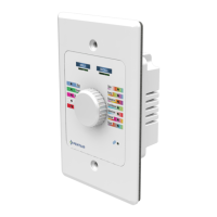
Dip switch SW3
Pushbutton SW5
Red LED:
Enter confirmation
Green LED:
Power ON
Rotary switch SW6
Rotary switch SW4
FIGURE 13 - Configuration of the actuator parameters.

 Loading...