to hold in the memory-lock but-
ton. Depressing the memory-lock
button turns on the LEDs and
locks the exposure for 10 seconds.
During the memory hold, the "P"
LED and the shutter-speed LED
flicker. On manual mode, the
memory-lock button has no func-
tion. If you depress the memory-
lock button on manual mode, the
"M" LED and the shutter-speed
LED flicker. However, the opera-
tion isn't affected.
10. The current version of the camera
has a cable-release socket at the
front, rewind side of the lens
mount. Shorting across the cable-
release socket releases the mirror.
11. The finder LEDs provide the low-
battery warning. If the LEDs
flash on and off, the batteries are
getting low. If the batteries are
too low for proper operation, the
LEDs won't turn on and the shut-
ter won't release.
12. The camera provides automatic
flash control with any Pentax
dedicated unit. In the manual
mode, the flash sets the shutter
speed to 1/100 if the shutter is set
to 1 /125 or faster. When the
flash charges, a lightning-flash
LED turns on in the finder along
with "M." The shutter-speed
LEDs turn out. If you set the
shutter to 1 /60 or slower, the
shutter delivers the selected shut-
ter speed. The lightning-flash
LED, the "M" LED. and the
shutter-speed LED noting the set-
ting turn on when the flash
charges. In the program mode,
the flash sets both the shutter
speed and the aperture. When the
flash charges, the "M" LED and
the lightning-flash LED turn on.
The shutter delivers 1/100.
SWITCH LOCATIONS AND
FUNCTIONS
1. Main switch. Sliding switch, lop
rewind end. Fig. I. In the on posi-
tion. Fig. 17, the main switch
connects battery voltage to PC
board TI00. With the main
switch in the off position, the
shutter won't release and the
LEDs won't turn on.
2. Self-timer switch. On main-
switch block. Fig. I 7. Sliding the
main switch all the way forward
connects battery power to the
circuit and closes the self-timer
switch. IC1 then delays the
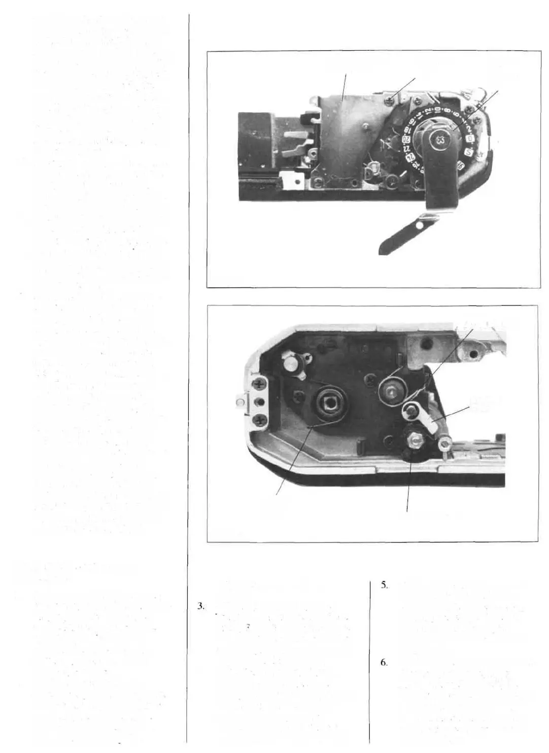
SHUTTER-SPEED
BASE PLATE
WINDING
SEAT
0-C2
FIGURE 7
TRANSPORT-
LATCH SPRING
RETURN
SPRING
C137
SPROCKET HOOK
FIGURE 8S
4.
mirror-release signal for 12
seconds.
SWS. Light-measuring switch.
Top contact on shutter-speed PC
board, tig. I. Pushing the release
button part way moves the SWS
contact against the center ground
contact. The LEDs turn on.
SWR. Release switch. Bottom
contact on shutter-speed PC
board. Fig. I. Fully depressing the
release button moves the center
ground contact against the
release-switch contact. lCI then
supplies the release signal to IC2.
Timing switch. In shutter block,
Fig. 21. The timing switch is
closed with the shutter cocked,
enabling the release. When the
1st curtain starts to run. the
timing switch opens to start the
timing cycle.
Wind-completion switch. Bottom
of camera, wind side. Fig. 2.
During the cocking cycle, the
wind-completion switch closes to
inhibit the shutter release. The
wind-completion switch opens
with the shutter fully cocked to
enable the release.
COUNTER-
DIAL
RETAINER
NUT
R LEVER
C105
 Loading...