Page | 7
Display Does Not Boot-Continued
d. If Pin-Out checks out correctly, test an alternate cradle
e. If pins 19/26 (Power) or 18/25 (Ground) fail, proceed to Step 4
f. If pins 24 or 10 fail, proceed to Step 5
4. If the Power/Ground from Vehicle pins (18, 19, 25, 26) are not properly powered, locate the Power Assembly. This should
be in the dash, most often near the fuse panel
a. Verify the cradle cable 2-Pin power connection is connected to the Power Assembly
b. Verify the Display Power fuse is in place and intact, with the fuse well seated
c. Test the vehicle power source and verify it is showing 11-24 volts
d. Test the Ground connection resistance to a known good location, testing with the vehicle key ON to make sure the
ground source is not floating: ohms should be less than 10 to a known-good source
e. If all power assembly/connection issues are ruled out, visually inspect the cradle cable for damage, particularly
near wear points. Replace the cable if needed.
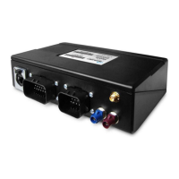
5. If the Cradle Cable Power/Ground from Vehicle pins check out but the PMG/OBC Pins (10 and 24) do not, locate the
PMG. This should be in the dash.
a. Verify the cradle cable is connected to the blue barrel connector of the PMG Auxiliary cable
b. Verify the PMG Auxiliary cable is connected to the PMG
c. Check the PMG LED
i. If the LED is not illuminated, then the issue is with PMG/PMG power. Proceed to Step 6
ii. If the LED is illuminated, either solid or blinking, disconnect the cradle cable blue connector from the PMG
Auxiliary cable to test
 Loading...