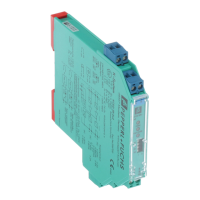
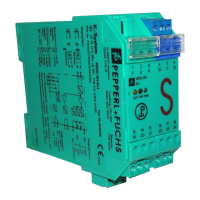
Functional Safety KCD2-SR-(Ex)*(.LB)(.SP), HiC282*
Planning
2018-12
13
DIP Switch Settings 1-channel Devices
DIP Switch Settings 2-channel Devices
LB/SC Diagnosis
The input loops of all versions are supervised, if the line fault detection is active (mandatory,
see datasheet). The related safety function is defined as the outputs are in fault state
(safe state), if there is a line fault detected.
Reaction Time
The reaction time for all safety functions is < 20 ms.
Function Mode KCD2-SR-(Ex)1.LB(.SP) HiC2821
Mode of operation
output I
normal mode S1 position I S1 position II
inverted mode S1 position II S1 position I
Assignment output II follow output I S2 position I S3 position I
LB/SC detection
1
1
This switch setting may not be used if output II is used for safety-relevant applications.
S2 position II S3 position II
Line fault detection ON S3 position I S2 position I
OFF
2
2
This switch setting may not be used if the device is used for safety-relevant applications.
S3 position II S2 position II
Table 3.1
Function Mode KCD2-SR-(Ex)2(.SP) HiC2822
Mode of operation
channel 1
normal mode S1 position I S1 position II
inverted mode S1 position II S1 position I
Mode of operation
channel 2
normal mode S2 position I S3 position II
inverted mode S2 position II S3 position I
Line fault detection
channel 1
ON S3 position I S2 position I
OFF
1
1
This switch setting may not be used if the channel is used for safety-relevant applications.
S3 position II S2 position II
Line fault detection
channel 2
ON S4 position I S4 position I
OFF
1
S4 position II S4 position II
Table 3.2
Note!
The fault indication output is not safety relevant.
Note!
See corresponding datasheets for further information.