Functional Safety KCD2-SR-(Ex)*(.LB)(.SP), HiC282*
Operation
2018-12
19
Proof Test Procedure
1. Put out of service the entire safety loop. Protect the application by means of other measures.
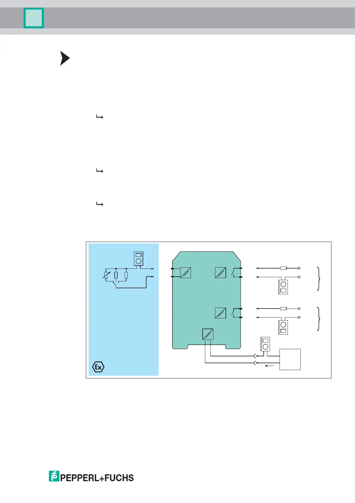
2. Prepare a test set-up, see figures below.
3. Simulate the sensor state by connecting a potentiometer, a resistor for short circuit
detection or by a resistor for lead breakage detection.
Test each input channel individually.
4. Connect a potentiometer of 4.7 k (threshold for normal operation) to the input.
The threshold must be between 1.4 mA and 1.9 mA, the hysteresis must
be between 170 µA and 250 µA.
- If the input current is above the threshold the relay must be activated for
normal mode of operation. The yellow LED lights up.
- If the input current is below the threshold the relay must be activated for
inverted mode of operation. The yellow LED lights up.
5. Connect a resistor R
SC
of 220 or a resistor R
LB
of 150 k to the input.
The device detects an external fault. The relay of the corresponding channel
must be de-activated. The red LED flashes.
6. Test both relay outputs with a specific current, e. g. 100 mA. To avoid electric shock,
use a test voltage of 24 V DC. Check that the relay contacts are open.
The relays must be de-activated. The relay contacts must definitely open.
7. Set back the device to the original settings for the application after the test.
8. Check the correct behavior of the safety loop. Is the configuration correct?
9. Secure the DIP switches to prevent unintentional adjustments.
Figure 5.1 Proof test set-up for KCD2-SR-(Ex)1.LB(.SP)
Usage in Zone 0, 1, 2/Div. 1, 2 only for KCD2-SR-Ex1.LB(.SP).
KCD2-SR-Ex1.LB
Zone 2
Div. 2
Zone 0, 1, 2
Div. 1, 2
Multimeter
(mA)
5
6
1+
2-
7
8
Multimeter
(mA)
Multimeter
(mA)
240 Ω/2.5 W
24 V DC
Multimeter
(mA)
240 Ω/2.5 W
24 V DC
9+
10-
I
II
24 V DC
Power
supply
I
supply
R
LB
R
SC