Do you have a question about the Perfect Prime TC0520 K and is the answer not in the manual?
Introduction to the datalogger thermometer and manual usage guidelines.
Critical safety precautions, environmental limits, and maintenance advice.
Specifies altitude, humidity, and operation ambient temperature limits.
Instructions for servicing, cleaning the case, and avoiding abrasives/solvents.
Definition of symbols like CE for EMC compliance.
Highlights the capabilities such as four-channel inputs and alarm functions.
Compatibility with K, J, E, and T type thermocouples.
Features 16,000 records/channel and instant recall function.
Includes USB connectivity and Windows software for data management.
Adjustable feature to conserve battery by powering off automatically.
Details temperature limits for different thermocouple types and measurement resolution.
Specifies measurement accuracy and how temperature affects it.
Defines data sampling frequency and battery type/lifetime.
Specifies acceptable temperature and humidity ranges for operation and storage.
Provides dimensions, weight, and a list of standard included accessories.
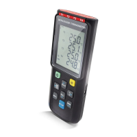
Explanation of various icons and indicators shown on the thermometer's screen.
Symbols for MIN, MAX, AVG values, and temperature units (°C/°F).
Icons for REC, FULL, MEM, ALARM, HOLD, and Power Off status.
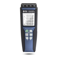
Visual representation of the thermometer with numbered components.
Labels for Thermocouple Input, USB, and all control buttons.
Highlights features like Tilt Stand and Battery Compartment.
How to turn the device on/off and control the LCD backlight.
Using the HOLD button to freeze readings and REC for data logging.
Saving readings to memory and retrieving stored data.
How to monitor and display maximum, minimum, and average readings.
Procedure to exit the MAX/MIN/AVG display mode.
Switching measurement units between Celsius (°C) and Fahrenheit (°F).
How to enter and exit the device's setup options.
Steps to enter setup, adjust parameters, and save changes.
Procedure to select the correct thermocouple type (K, J, E, T).
Setting the time interval for automatic data recording.
Adjusting readings to correct for thermocouple measurement inaccuracies.
Configuring high and low temperature alarm limits for channel T1.
Enabling the display of temperature difference between T1 and T2.
Setting the inactivity period before automatic power off.
Configuring the year, date, and time for accurate logging.
Using buttons to choose thermocouple type K, J, E, or T.
Configuring the time interval for data storage in minutes or seconds.
Compensating thermometer readings for thermocouple probe inaccuracies.
Turning alarms on/off and setting Hi/Lo limits for T1.
Enabling or disabling the T1-T2 subtraction mode via button press.
Selecting auto power off time from various options.
Setting the device's internal clock for time-stamped data.
Procedure to turn off, hold buttons, and confirm memory clearing.
Procedure to clear stored readings from instant memory.
Instructions for establishing a connection via USB or Bluetooth.
Steps for replacing batteries when low voltage is indicated.
Guidance on annual calibration and proper device cleaning.
Recommendation to calibrate the thermometer once per year.
Advice on cleaning the device using specific types of cloths.
Details on the SE-520 software, system, and hardware requirements.
Guide to connecting the thermometer, starting software, and checking status.
Selecting the data sampling rate within the Real-Time Graph window.
Instructions for starting and stopping the data recording process.
Procedure for saving graph window data using the File | Save option.
Choosing between binary, text, and EXCEL file formats for saving data.
Note on potential issues with CSV file format and decimal separators.
Steps to load data from the thermometer into the SE520 software.
Overview of the File, Real Time, Data Logger, View, and Window menus.
Functions available under the File menu: Open, Save, Print, Exit.
Options for controlling the meter via Panel Window and Real-Time Graph.
Starting and stopping the collection of real-time data.
Loading recorded data and viewing progress indicators.
Displaying loaded data sets with start date, time, rate, and record numbers.
Visual representation of recorded data with time and channel information.
Icons for displaying statistics and selecting cursor types.
Using mouse cursor as cross sign for marking or '|' for annotating.
Functionality to display channels separately or combined in the graph.
Adjusting Y-axis maximum and minimum scales for graph display.
Using mouse actions to zoom into graph areas and revert.
Choosing which channels to display in the graph view.
Answers to common queries about software uninstallation and graph features.
Steps to remove the SE520 software from the computer.
Procedure for zooming into specific areas of the graph.
Explanation of potential data loss during fast sampling and mitigation.
| Sampling Rate | 1 second to 24 hours |
|---|---|
| Display | LCD |
| Connectivity | USB |
| Resolution | 0.1°C / 0.1°F |
| Logging Capacity | 16, 000 readings |
| Battery Life | 1 year |
| Probe Type | K-type thermocouple |
| Operating Temperature | -20°C to +60°C (-4°F to +140°F) |