Specifications are subject fo change without notice
OPERATION
SAFETY IMFORMATION
1.
Always wear eye protection and other safety equipment such as dust
mask, non-skid safety shoes, hard hat, hearing protection, and work
gloves. Using safety equipment that fits the appropriate conditions will
reduce personal injuries.
2. Maintain all labels on the tool. They contain important safety information. If
unreadable or missing, contact Performance Tool for a replacement label.
3. Never exceed the maximum weight limit of 700 Pounds.
4. Do not work on an engine that is only supported by the Engine Support. Do
not intentionally jar, jostle or move the engine. Moving the engine in any way
creates a safety hazard. This may cause the engine support to jump the fender
channels and fall resulting in serious personal injury or property damage.
5.
Never work underneath an engine while it is supported only by the
Engine Support.
6.
The warnings, precautions, and instructions discussed in this instruction
manual cannot cover all possible conditions and situations that may occur.
It must be understood by the operator that common sense and caution are
factors which cannot be built into this product, but must be supplied by
the operator.
1. Read the vehicle owner’s manual to determine the location of its lifting points.
2. Never try to move a running or hot engine. Give sufficient time for the engine to cool
down entirely before beginning any operations.
3. Park the car on a flat surface, apply the parking brakes and chock the wheels.
4. Loosen Wing Bolts (10) and spread the standing base assemblies (5.1). Place the feet
of the base assembly over the lips adjacent to the fenders of the car. Center the
engine support bar assembly over the engine, tighten the Wing Bolts (10).
5. Attach the Chains (6) to the engine at the appropriate lifting points. Some models
have a lifting plate mounted to the top of the engine for lifting. If not then loop the
chains around the engine and secure to a place capable of holding the weight, not to
exceed 700 pounds.
6. Attach the other end of the chain to the bottom of the Support Hook (7).
7. Turn the Handles (9) clockwise until the Chains are taut and the engine is held securely
in place.
8. Loosen the engine mounts and turn the Handle (9) slowly clockwise until the engine’s
weight is supported by the chains.
8. Never work on the engine while it is supported only by the Engine Support. Moving the
engine while it is suspended only by the Engine Support can cause the Engine
Support to fail or shift, resulting in serious personal injury and/or property damage.
9. To prevent accidents, lower and reconnect the engine when finished working. The
Engine Support is not intended to be used as a long-term suspension device.
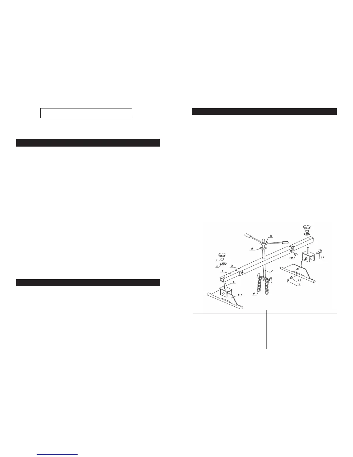
ASSEMBLY
1. Place the Standing Block (5) on the Standing Bracket (5.1). Hold in place with
clevis pin (11), washer (12) and pin (13).
2. Use provided hand knob (1) and washer (2), attach standing base assembly
(5/5.1) to extension (4). Repeat on the other side of the Engine Support. Tighten
knobs (1).
3. Slide the stand /extension assembly into the crossbeam (3). Adjust to t and
tighten bolts (10). Slide the hook (7) through beam (3) and secure with the wash-
er (8) and handle (9). The hook can be adjusted once the chain (6) is attached to
the engine, or engine bracket.
This Engine Support Bar is designed for engines 700 lbs. or less. Enables parts
or mechanisms underneath the engine to be accessed for repair or removal.
Provides time savings and safety to the mechanic.
NO. DESCRIPTION Q’TY NO. DESCRIPTION Q’TY
1 Handwheel ................................... 2 7 Hook .........................................1
2 Washer ......................................... 2 8 Washer......................................1
3 Crossbeam ................................... 1 9 Handle......................................1
4 Extension ...................................... 2 10 Bolt ........................................2
5, 5.1 Base ............................................. 2 11 Pin .........................................2
6 Chain ............................................ 1
12 Washer......................................2
13 Pin.............................................1
 Loading...