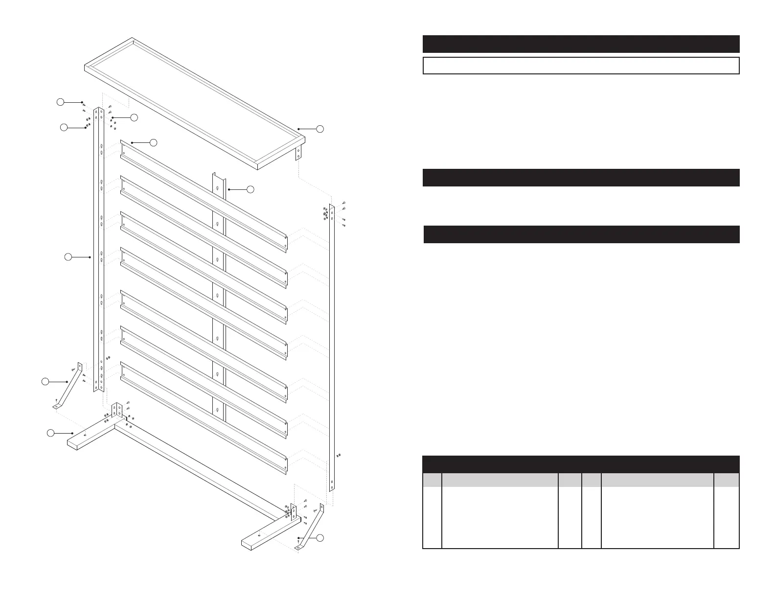
PARTS LIST
TOOLS REQUIRED
ASSEMBLY INSTRUCTIONS
10
6
1
3
2
5
4
7
8
9
1.Placethetoptrayupsidedownonaatsurface.
2. Position one of the L-bar frame legs on the inside of the brackets on the
tray.NOTE:Theteardropshapedholesshouldbeonthelongersideofthe
tray,withthelargercircleportionoftheopeningsfacingdown.
3. Usealargescrew,washerandnuttofastentheL-barframelegstothetoptray
bracketsonbothsides.
4. Placethebaseontheendofthelegs,withthelegsinsidethebracketsonthe
base,andfastenwithalargescrew,washerandnut.
5. Placethebottombinsupportbracketonthebottomsetofholesinthelegs.
6. Aligntheholesinthebasesupportbracketswiththethreadedholesonthe
base,andholesinthelegs.Fastenthetopholeswithalargescrew,washer
andnut.Fastenthebottomholeswithtwosmallmachinescrews.
7. Insertremainingbinsupportbracketsontothelegs.Makesurethe3holesin
thesupportbracketareclosertothetop.
8. Alignthe vertical support bracket with thebolts on back of the binsupport
brackets,andlockintoplace.
No. Description Qty.
1 Base 1
2 BaseSupportBrackets 2
3 L-BarFrameLegs 2
4 BinSupportBrackets 7
5 VerticalSupportBracket 1
SPECIFICATIONS
NOTE:Specicationsaresubjecttochangewithoutnotice.
SmallRedBins:........................................................ 32(5-1/2x3-1/4in.)
LargeBlueBins:.............................................................. 15(8-1/4x5in.)
RackHeight:............................................................................... 45in.Tall
RackWidth:............................................................................. 37in.Wide
RackDepth:.............................................................................12in.Deep
Construction:...........................................................Powder Coated Steel
ReplacementPartsNo.W5193HW............... Hardwarekit(Nuts&Bolts)
No. Description Qty.
6 TopTray 1
7 LargeMachineScrews 18
8 Round Washers 18
9 HexNuts 18
10 SmallMachineScrews 2
•#2Phillipsheadscrewdriver
•10mmwrenchorsocketandratchet
 Loading...