POWER RELAY INSTALLATION INSTRUCTIONS
Maximizing Ignition Energy with a PerTronix Power Relay
Ignitor II and Ignitor III ignition systems require a full + 12V power connection between the ignition switch and
the positive coil terminal. Most AMC,Chrysler, and Ford vehicles are equipped with OE resistance wires or ballast
resistors. All pre-1974 (Non HEI) GM vehicles are equipped with OE resistance wire. To get the full benet of our
high performance ignition systems the primary resistance needs to be eliminated or bypassed. In most cases, adding
a PerTronix ignition power relay may be easier than cutting into the vehicles wiring harness and replacing wires.
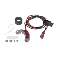
PARTS INCLUDED WITH POWER RELAY KIT
• 30 Amp auto relay
• relay socket and harness
• 3 Amp 400 volt diode
• self tapping sheet metal screw
• male and female connectors
• battery ring terminal
• coil ring terminal
1. Determine the best location to mount the relay socket and
harness. Common mounting locations include the re wall
or inner fenderwell. Make sure the location you choose
enables the wires to be routed clear of headers, exhaust
manifolds, fan blades and belts. Also make sure each wire
will reach its destination.
2. Drill a small pilot hole in the desired location and use the
provided sheet metal screw to mount the socket.
3. Attach the short black ground wire to a good clean ground.
4. Disconnect the ignition switch wire from the coil positive
terminal. Use the provided male and female tab connec-
tors to attach the ignition switch wire directly to the small
purple wire from the power relay.
5. Run the orange wire from the power relay to the coil posi-
tive terminal. Determine the proper wire length and cut the
wire to size. Attach the provided ring terminal. Attach the
orange wire to the positive coil terminal.
6. Run the large red wire to the battery positive terminal.
Determine the proper length and cut the wire to size. Attach
the large ring terminal. Fasten the large red wire to the bat-
tery positive post.
7. Insert the relay into the relay socket.
8. Test for proper operation of the circuit by starting the en-
gine and then turning ignition key o. If engine continues
to run after the key is turned o, remove the relay to stop
the engine and proceed to step 9 on the back. If the engine
stops running when key is turned o, your installation of
the ignition power relay is complete.
+ 12 VOLT
FROM BATTERY
GROUND
IGNITION
SWITCH
OEM BALLAST
RESISTOR OR
RESISTANCE WIRE
POWER RELAY
Coil
+ Terminal
LARGE RED
SMALL PURPLE
ORANGE
BLACK
0000-008770 07/12