J7'
PHII,CO
TRANSITONE
SERVICB BROADCAST
Frc.4.
Morars 8 AND
12
(Code
121)
I. F.
175 K. C.
R.
F. Compensators.
Alter the
detector-oscillator
has been
padded-at 1400
K.
C.,
adjust the
first and
second
R' F' Con-
densers
on tuning
condenser
at
1400 K' C.
Low
Frequeniy
Condenser.
Set
the signal
generator
to 700
K. C.
Now tune the
Receiver
sharply.
Adjust
the
L' F'
con-
d.enser
shown
near the
center
oI
Figs. 3
and 4.
During
this
op-
eration
the tuning
condenser
must
be shiited
and the
com-
pensators
must
be
adjusted
to bring
in the
maximum
signal.
After
this
has been
done,
check
the adjustment
of
the
high-
frequency
condenser
at
1400
K' C. again.
MODEL
10
I. F.
A
new style
I. F. transformer
complete with
adjusting
condensers
is
used
in the
Model
10.
The
condensers
are
placed
in the top
of the shield
can'
one
above the
other.
The
primary
L F'. condenser
is
adjusted
by means of the screw'
siot, accessible
through the
hole in the top of the shield can.
The
secondary
is
adjusted
b1' means of the small
hex nut, also acces-
sible through the
hole in the top of the shield.
Remove the speaker
lid from the
Receiver and disconnect the
antenna lead
from
the
Receiver.
Remove the
giid
cap
lrom the
64.7 tube.
(For
location
see
Fig. 5.)
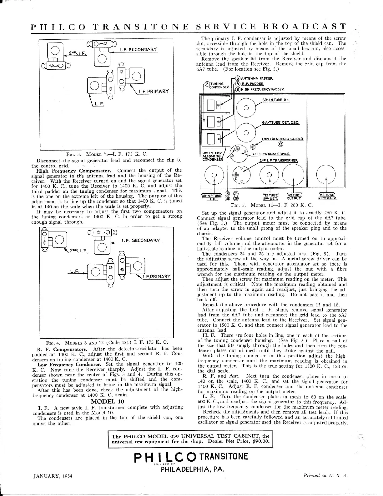
Frc.
5.
Moonr 10-I.
F. 260 K.
C.
Set
up
the
signal
generator
and
adjust it to exactly
260
K.
C.
Connect
signal
generator
lead
to the
grid
cap of the 6A7 tube.
(See
Fig.
5.)
The output meter
must
be
connected
by
means
of an adapter to
the
small
prong
of the speaker
plug
and to the
chassis.
The Receiver
volume control must be turned on to
approxi-
mately
full volume
and
the attenuator
in
the
generator
set for a
half-scale reading
of the output meter.
The condensers
24 and
26
are adjusted first
(Fig.
5). Turn
the adjusting
screw all
the
way
in. A
metal screw driver can
be
used
for
this.
Then, with
generator
attenuator
set
so there is
approximately
half-scale reading, adjust
the
nut
with
a fibre
wrench
for the maximum reading on the output meter.
Then adjust
the screw
for
maximum reading on
the
meter.
This
adjustment
is critical. Note
the maximum
reading
obtained and
then turn
the screw
in
again and readjust,
just
bringing
the ad-
justment
up
to the
maximum reading.
Do not
pass
it
and
then
back off.
Repeat the above
procedure
with
the
condensers
15
and
18.
After adjusting the first I. F.
stage,
remove
signal
generator
lead from the 6A7 tube and reconnect the
grid
lead
to the 6A7
tube.
Connect the
antenna lead
to the Receiver.
Set signal
gen-
erator
to 1500 K.
C.
and then connect signal
generator
lead
to the
antenna
lead.
H. F. There
are
four
holes in line,
one
in
each of
the
sections
of the
tuning
condenser
housing.
(See
F'ig. 5.) Place
a nail
of
the size that fits snugly through the holes
and then
turn
the con-
denser
plates
out of mesh until
they strike
against the nail.
With
the tuning condenser in
this
position
adjust
the high-
{requency condenser
until
the
maximum
reading is
obtained
in
the output meter.
This is
the true
setting for
1500
K.
C.,
150
on
the
dial scale.
R. F. and
Ant.
Next
turn
the condenser
plates
in
mesh
to
140 on the scale,
1400
K.
C., and set the
signal
generator
for
1400 K. C. Adjust
R. F.
condenser
and the
antenna
condenser
for maximum
reading on
the
output
meter.
L. F.
Turn
the
condenser
plates
in
mesh
to
60 on the
scale,
600
K.
C.,
and readjust
the
signal
generator
to
this frequency.
Ad-
jus]
the
lorv-frequency condenser
for
the maximum
meter reading.
Recheck the
adjustments and then remove
all test
leads.
lf
this
procedure
has been carefully followed
and
an accurately
calibrated
oscillator or signal
generator
used,
the Receiver
is
adjusted
properly.
r_
^--l
dG@ b
lf )l T--rrT t.F.sEcoNDARY
I
\--l
I zxo..l.F. I :--]--==---
@
ti/l-
#{^r
r^-rcl^FUl
tgi'l
ffV*.PR,r4ARY
\E
\!=E
Frc. 3.
MoouL
7.-I.
F. 175
K C.
Disconnect
the signal
generator
lead and
reconnect
the clip
to
the control
grid.
High
Frequency Compensator.
Connect
the
output
-of
the
signal
generalor
to
the
antenna
lead and
the housing
of the
Re-
ceiver. With
the
Receiver turned on
and
the.signal
generator
set
for 1400 K. C.,
tune the Receiver
to
1400 K. C.
and adjust
the
third
padder
on the
tuning
condenser
for
maximum
signal.
This
is
the
bne on the extreme
left of the
housing.
The
purpose
of
this
adjustment
is to
line
up the
condenser
so that
1400 K. C.
is
tuned
in at 140 on
the
scale
when
the scale
is set
properly.
It may be
necessary
to adjust
the
first
two
compensators
on
the
tuning condensers
at 1400 K. C.
in
order
to
get
a strong
enough signal through.
The PHILCO
MODEL
059
UNMRSAL
TEST CABINET' the
universal
test equipment
for the
shop.
Dealer Net
Price,
tgo.oo.
PH
lLCOrnnruslroNE
JANUARY,
1934
PHILADELPHIA,
PA.
Printed in
U. S. A.
 Loading...