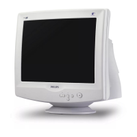
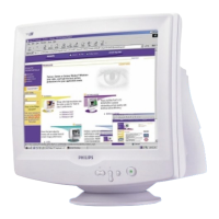
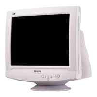
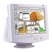
17” CDT Color Monitor 107S7
77
2.7.3 LED indicator
• Normal on - Green.
• Active off - Green Blinking (1sec on / 1sec off).
• Switch off - Blank.
2.7.4 Monitor status information
•
Self-test feature - “CHECK SIGNAL CABLE” message appears when video cable
is disconnected.
•
Out of scan range - “FREQUENCY IS OUT OF RANGE” appears when input H-sync
or V-sync out of range.
• Resolution & H/V input - Shown in OSD menu “EXTRA CONTROLS”.
2.7.5 Power connector
•
AC socket 3-pin IEC-320-C13, at rear side.
2.7.6 Video input connector/Video cable
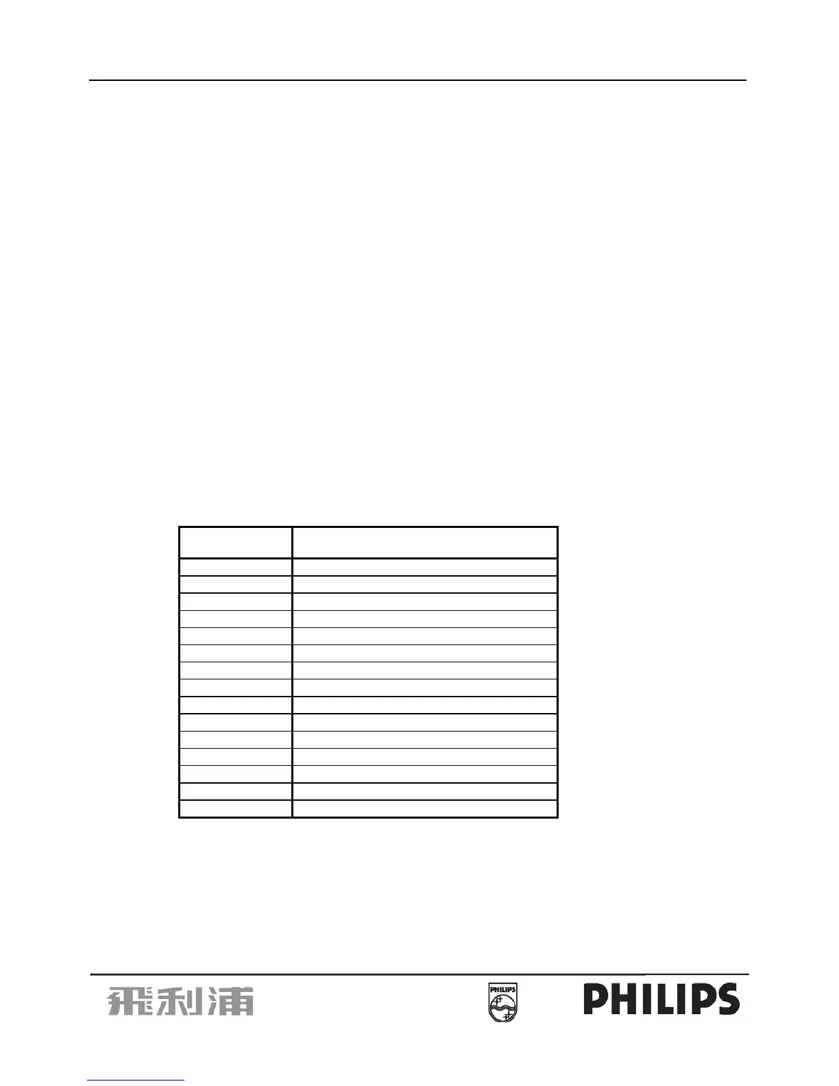
• 1.5m non-detachable fly-in video cable with D-Sub 15 pin male blue connector, pin assignment of D-Sub:
Pin
Function
1 Red video
2 Green video
3 Blue video
4 GND
5 Self test
6 Red GND
7 Green GND
8 Blue GND
9 +5V (Supply from PC for DDC circuit)
10 Sync GND
11 GND
12 DDC serial data
13 H-sync
14 V-sync
15 DDC serial clock
•
H-sync line impedance must be within 50 ~ 70Ω (TDR measurement).
• V-sync line impedance should be within 40 ~ 70Ω (TDR measurement).
• RGB signal lines must be 75Ω ± 5% coaxial.
• R, G, B coaxial shield must connect to D-Sub metal shell.


 To Next Page