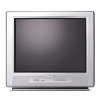
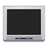
Do you have a question about the Philips 21PT5421/12 and is the answer not in the manual?
Details on reception, tuning, colour, sound systems, and A/V.
Describes rear and side connections for various inputs/outputs.
Detailed pinout and specifications for rear connection ports.
Details on side AV input and headphone connections.
Overview of the main chassis components and their layout.
Essential safety regulations and precautions for repair.
Guidelines for post-repair checks and returning the set to original condition.
Critical warnings regarding high voltage, ESD, and component handling.
Notes on interpreting resistor and capacitor values in schematics.
Procedure and precautions for reworking Ball Grid Array integrated circuits.
Guidelines for handling lead-free solder and components.
Precautions to avoid electrical shock and protect components during service.
Step-by-step guide for safely removing the rear cover.
Instructions for positioning the main panel during service.
Steps for correctly reattaching the rear cover after service.
Accessing and navigating the TV's service mode for adjustments.
Flowchart to diagnose power supply issues.
Diagram showing audio and video signal flow.
Diagram illustrating the power supply unit's architecture.
Diagram showing the Inter-Integrated Circuit communication bus.
Overall system block diagram illustrating major modules and connections.
Circuit diagram for the MCU section of the main board.
Circuit diagram for the video processing section of the main board.
Circuit diagram for the audio processing section of the main board.
Circuit diagram for the power supply section of the main board.
Circuit diagram for the deflection circuitry of the main board.
Circuit diagram for the CRT panel.
Circuit diagram for SCART connection interfaces.
Top-side component layout of the main board.
Bottom-side component layout of the main board.
Circuit diagram for the MCU section of the 05TA085-6 main board.
Circuit diagram for the video section of the 05TA085-6 main board.
Circuit diagram for the sound section of the 05TA085-6 main board.
Circuit diagram for the power section of the 05TA085-6 main board.
Circuit diagram for the deflection circuitry of the 05TA085-6 main board.
Circuit diagram for the CRT panel of the 05TA085-6 main board.
Circuit diagram for SCART connections on the 05TA085-6 main board.
Top-side component layout of the 05TA085-6 main board.
Bottom-side component layout of the 05TA085-6 main board.
Circuit diagram for the side I/O panel connections.
Top-side component layout of the side I/O panel.
Procedures for physical adjustments like voltage and geometry.
Procedure for adjusting the V100 potentiometer for 110V DC.
Accessing service mode for software-based alignments.
Procedure for adjusting the G2 control for picture display.
Alignment procedure for the tuner and intermediate frequency stages.
Procedure for adjusting the Automatic Gain Control parameter.
Detailed descriptions of key hardware components like MCUs.
Alphabetical list of abbreviations used in the manual.
Explanation of how the TV system's functions operate.
Description of the Automatic Frequency Control system.
Controls for picture settings like brightness, contrast, and screen format.
Details on sound modes, volume control, and mute function.
Description of external input modes like SCART (EXT) and AV.
Block diagrams and pin layouts for integrated circuits.
Data sheet for the ST24C16 EEPROM IC.
Data sheet for the ST92195CD microcontroller IC.
Data sheet for the STV224X video processor IC.
Data sheet for the TDA2822 audio amplifier IC.
Data sheet for the IC1QS01 power supply controller IC.
Data sheet for the LM317 voltage regulator IC.
Data sheet for the LM7805 voltage regulator IC.
Data sheet for the TDA1771 deflection amplifier IC.
Details of the first release of the service manual.
Information on revisions and additions made in manual version 1.
| Display Type | CRT |
|---|---|
| Screen Size | 21 inches |
| Aspect Ratio | 4:3 |
| Teletext | Yes |
| Tuner | Analog |
| Connectivity | SCART |


 Loading...