16
TPT1.1A LA
4. Mechanical Instructions
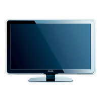
Front view
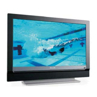
Back view
Step 1. Remove the stand.
Remove the 2 screws as Fig.2.
Fig.3
Fig.2
Fig.1
Fig.6
Fig.7
Fig.4
Fig.5
4. Mechanical Instructions
Index of this chapter:
4.1 Assy/Panel Removal
4.2 Set Re-assembly
4.1 Assy/Panel Removal
Notes: Please put your machine on soft material to avoid to scrape
panel when you disassemble it.
Step 2. Remove the Speaker.
Remove the 5 screws as Fig.3.
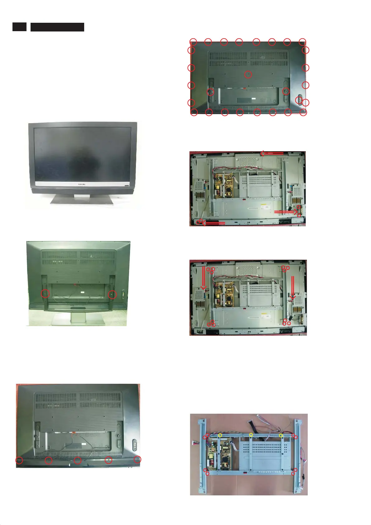
Step 4. Remove the Back cover as Fig.4~5.
a.
Remove the 28 screws on the bottom side as Fig.4.
b. Remove the back cover as Fig.5.
Step 5. Remove the Key, Side AV, IR board.
a. Remove the 4 screws and disconnect the 3 cables to r
as Fig.5.
emove the
Key, Side AV, IR board
Step 6. Remove the Main Frame.
a. Remove the 12 screws and disconnect 2 cables to remove the Main
Frame as Fig.6.
Step 7. Remove the Scaler and Power board.
a. Remove the 8 screws to remove the MF-LPL-L/R as Fig.7.
b. Remove the 6 screws to remove the VESA-BKT-LR/M as Fig.7~8.
c. Remove the 12 screws to remove the MS-Scaler as Fig.9.
d. Remove the 7 screws and disconnect 3 cables to remove
the Power board as Fig.10.
e. Remove the 18 screws and disconnect 6 cables to remove
the Scaler board as Fig.10.
 Loading...