Technical Specs, Diversity, and Connections
EN 3TPN16.2E LA 2.
2016-Jul-15
back to
div. table
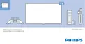
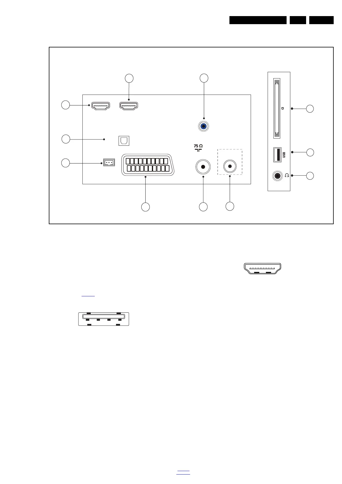
2.3 Connections
Figure 2-1 Connection overview
Note: The following connector colour abbreviations are used
(acc. to DIN/IEC 757): Bk= Black, Bu= Blue, Gn= Green,
Gy= Grey, Rd= Red, Wh= White, Ye= Yellow.
2.3.1 Side Connections
1 - Common Interface
68p- See figure 10-4-6
jk
2 - USB 2.0
Figure 2-2 USB (type A)
1-+5V k
2 - Data (-) jk
3 - Data (+) jk
4 - Ground Gnd H
3 - Head phone (Output)
Bk - Head phone 80 - 600 / 10 mW
ot
2.3.2 Rear Connections
4 - Audio - In: Left / Right, VGA
Bu - Audio L/R in 0.5 V
RMS
/ 10 kW jq
5 - HDMI 2: Digital Video - In, Digital Audio with ARC -
In/Out
Figure 2-3 HDMI (type A) connector
1 - D2+ Data channel j
2 - Shield Gnd H
3 - D2- Data channel j
4 - D1+ Data channel j
5 - Shield Gnd H
6 - D1- Data channel j
7 - D0+ Data channel j
8 - Shield Gnd H
9 - D0- Data channel j
10 - CLK+ Data channel j
11 - Shield Gnd H
12 - CLK- Data channel j
13 - Easylink/CEC Control channel jk
14 - ARC Audio Return Channel k
15 - DDC_SCL DDC clock j
16 - DDC_SDA DDC data jk
17 - Ground Gnd H
18 - +5V j
19 - HPD Hot Plug Detect j
20 - Ground Gnd H
TV ANTENNA
VGA / DVI
AUDIO IN
DIGITAL
AUDIO OUT
SCART
(RGB/CVBS)
SE
RV.U
HDMI 1
ARC
HDMI2
SAT
20060_001.eps
1
2
3
4
5
6
7
8
9
10
11
Side ConnectorsRear Connectors
(Optional)
1 2 3 4
10000_022_090121.eps
090121
10000_017_090121.eps
090428
19
1
18 2
 Loading...