83
APPENDIX C
Installation Checklists
(A simplified guide for those who are already familiar with installing and programming Allegiant systems.)
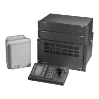
MAIN BAY HARDWARE INSTALLATION
þ Unpack equipment and verify that items have
been received without carrier damage.
þ Install power supply (do not turn ON) and CPU
module.
þ If applicable, install bay into EIA 19-inch rack
(remember to remove rubber bumper foot
pads).
þ Install video input module(s) following proper
termination procedures. Install video output
module(s).
þ Connect camera inputs and monitor outputs to
appropriate connections on equipment bay(s).
þ Connect system keyboards, any alarm interface
unit(s), and any signal distribution unit to main
bay.
þ Set CPU DIP switches to activate desired
features.
þ Apply main AC power to equipment.
þ Verify system is operating properly then begin
appropriate programming.
PROGRAMMING VIA SYSTEM KEYBOARD
þ Enter system time (User Function 7) and date
(User Function 8). Enter Camera ID titles (User
Function 9), and if desired, adjust monitor
overlay displays (User Function 4, 5, & 6 or 24,
25 & 26).
þ Enter desired Sequences.
þ Configure and test alarm response mode.
SATELLITE CONFIGURATION
HARDWARE INSTALLATION
Main Site:
þ Install main Allegiant bay and appropriate
accessory products accordingly. Verify biphase
control code line is run to each satellite site.
þ Attach Trunk line inputs, local camera inputs,
and monitor outputs to main Allegiant bay.
Apply main AC power to equipment.
þ Program Camera ID table using optional
TC8850 Graphical User Interface software or
optional TC8x59 Master Control Software
package.
þ Switch all unused monitor outputs located at
main site to display a ‘local’ camera input.
Satellite Site(s):
þ Install satellite switcher and appropriate
accessory products accordingly.
þ Connect biphase code line to TC8780 Data
Converter unit and configure according to
desired satellite address and switcher’s baud
rate.
þ If necessary, program satellite switcher for
desired camera titles and any other related
requirements.
 Loading...