For measuring point 28 and 33 put the player
in
the service
shell on CD drive test mode
2.
The voltage accross point 28
and GND should
be
:
7.2.2.6
Clock
signal µP
IC7475
Measuring point 29 : clock signal f
=
4MHz.
7.2.2.7
Decoder
signals
Play track
1 of testdisc 5.
The signal accross measuring point
31
and GND should be:
Insert testdisc 5 and put the player
in
the service shell on
CD drive test mode 2.
The signal accross measuring point 32 should be :
Measuring point
34 :
clock signal f
= 11.289.600 Hz.
Voltage accross measuring point 36 and
37:
775 mV
/DC±
10%
Measuring points
38:
LOW. If the blackdot track of testdisc
SA
is played then pulses activity should be measured on
this point.
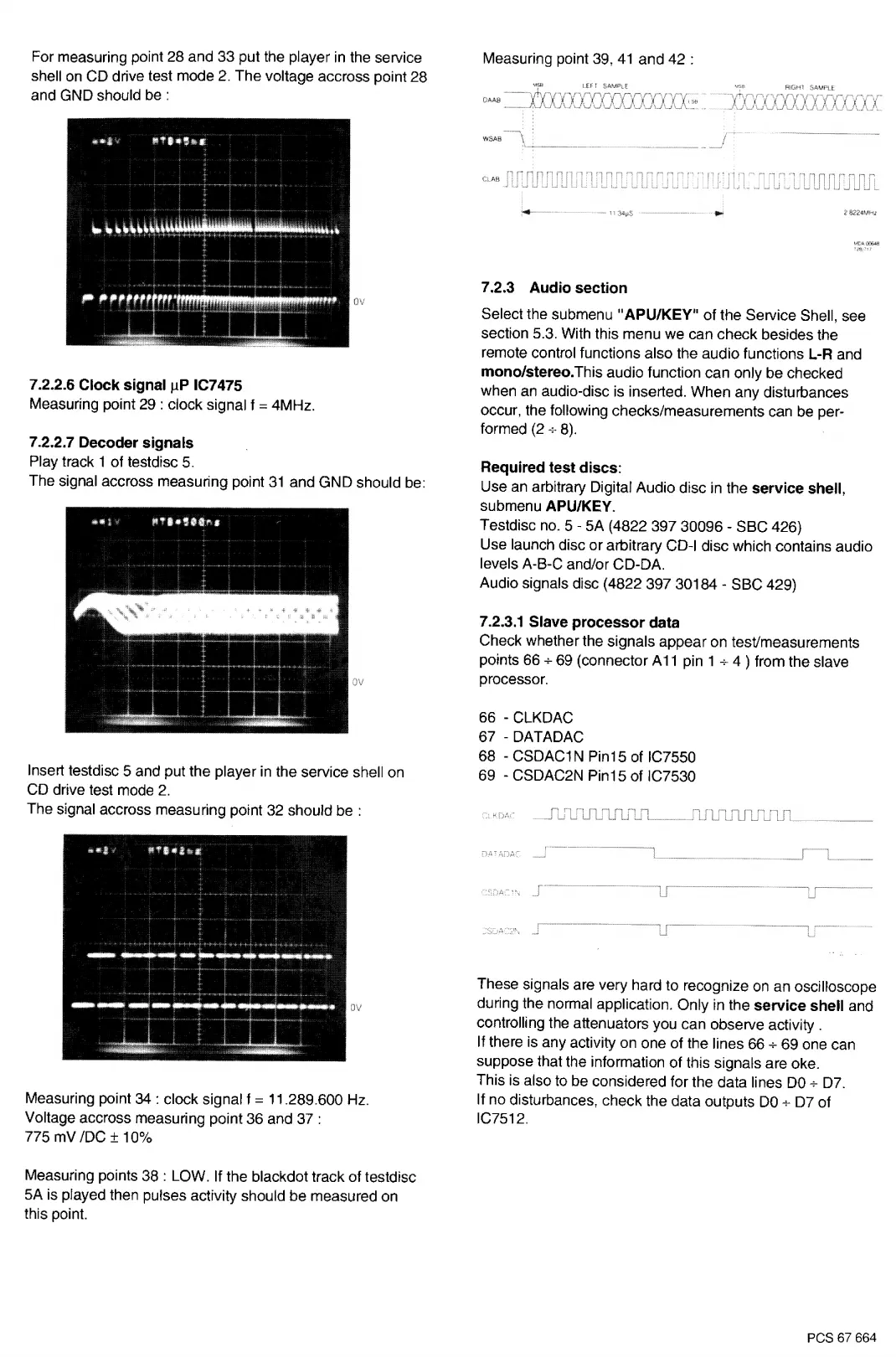
Measuring point 39,
41
and 42 :
.--
AB
......
~-
...
7 .2.3 Audio section
Select the submenu
"APU/KEY"
of
the Service Shell, see
section 5.3. With this menu we can check besides the
remote control functions also the audio functions
L-R
and
mono/stereo.This
audio function can only be checked
when
an
audio-disc is inserted. When any disturbances
occur, the following checks/measurements can be per-
formed (2-,.
8).
Required test discs:
Use
an
arbitrary Digital Audio disc in the
service shell,
submenu
APU/KEY.
Testdisc no. 5 -
SA
(4822 397 30096 - SBC 426)
Use launch disc or arbitrary CD-I disc which contains audio
levels A-B-C and/or CD-DA.
Audio signals disc (4822 397 30184 - SBC 429)
7.2.3.1 Slave
processor
data
Check whether the signals appear on test/measurements
points 66
+
69 (connector A
11
pin
1
+
4 ) from the slave
processor.
66
-
CLKDAC
67 -
DATADAC
68 - CSDAC1 N Pin15 of IC7550
69 - CSDAC2N Pin15 of IC7530
These signals are very hard to recognize
on
an oscilloscope
during the normal application. Only
in
the
service shell
and
controlling the attenuators you can observe activity .
If there
is
any activity on one of the lines 66
+
69 one can
suppose that the information
of
this signals are oke.
This is also to be considered for the data lines
DO+
D7.
If no disturbances, check the data outputs
DO-,.
D7 of
IC7512.
PCS 67 664
 Loading...